
High-efficiency, IEC/CE/GOST certified oil-immersed transformer for 20kV medium-voltage distribution networks
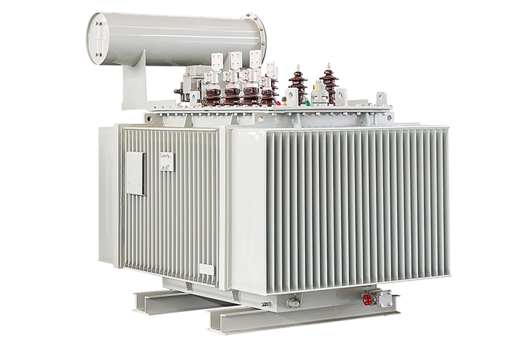
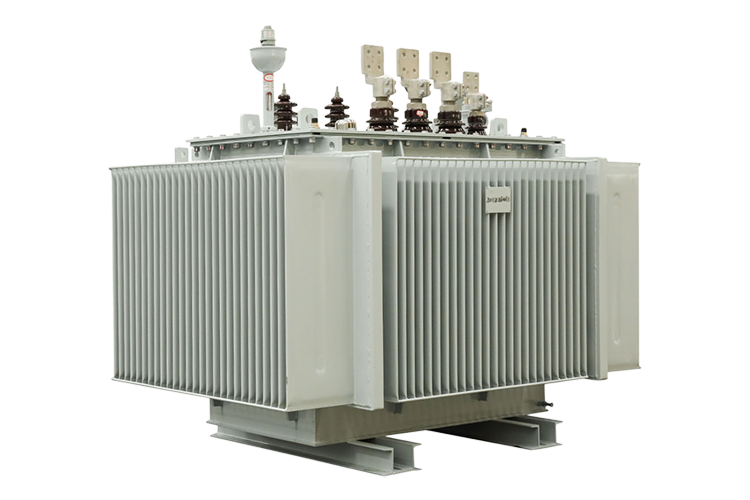
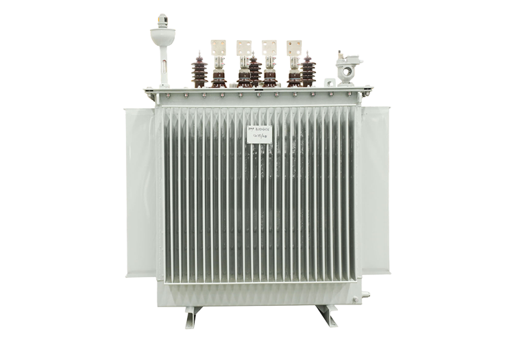
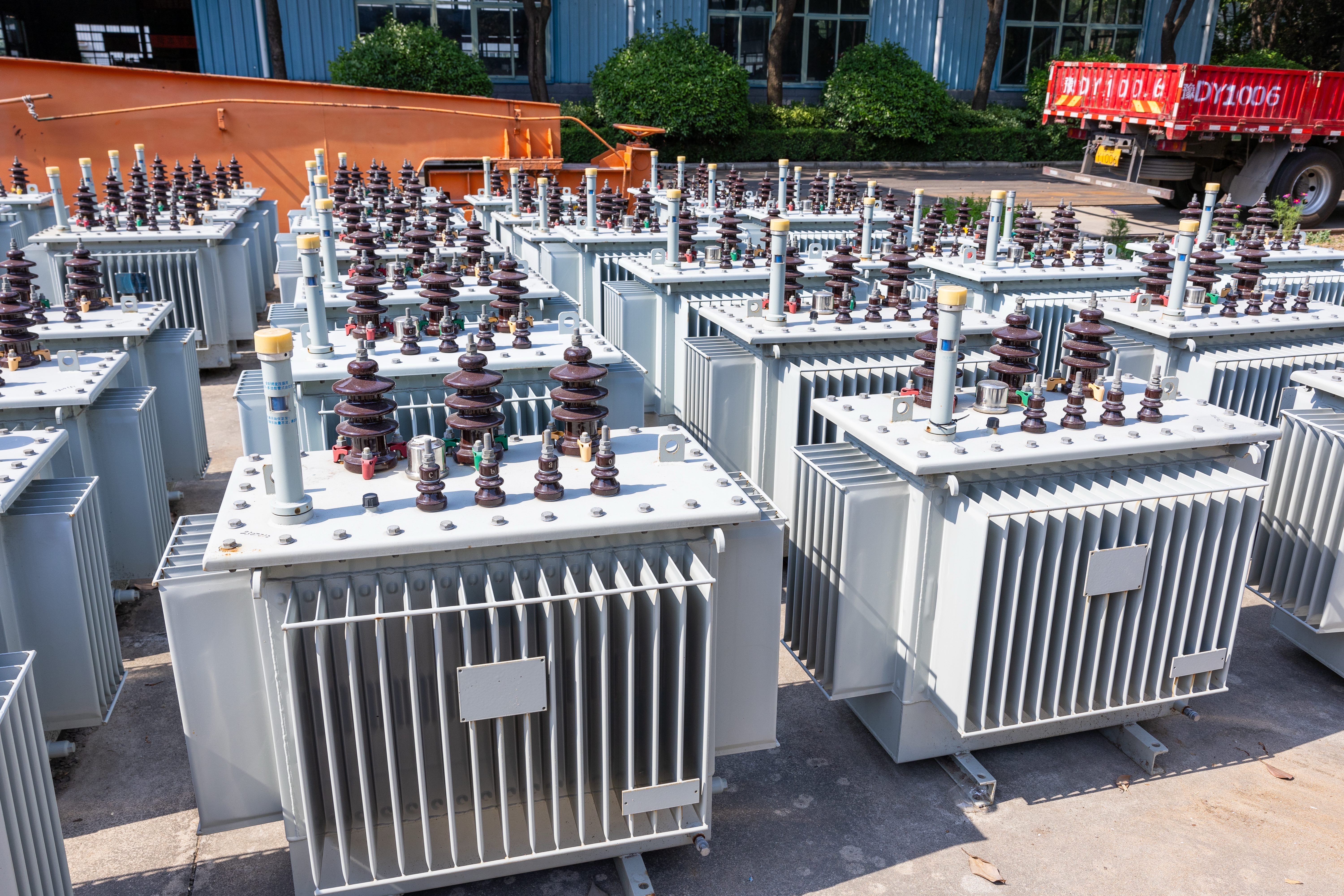




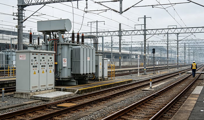
Optional on-load tap changer (OLTC) enables real-time voltage adjustment without power interruption, stabilizing supply for sensitive industrial loads and renewable integration.
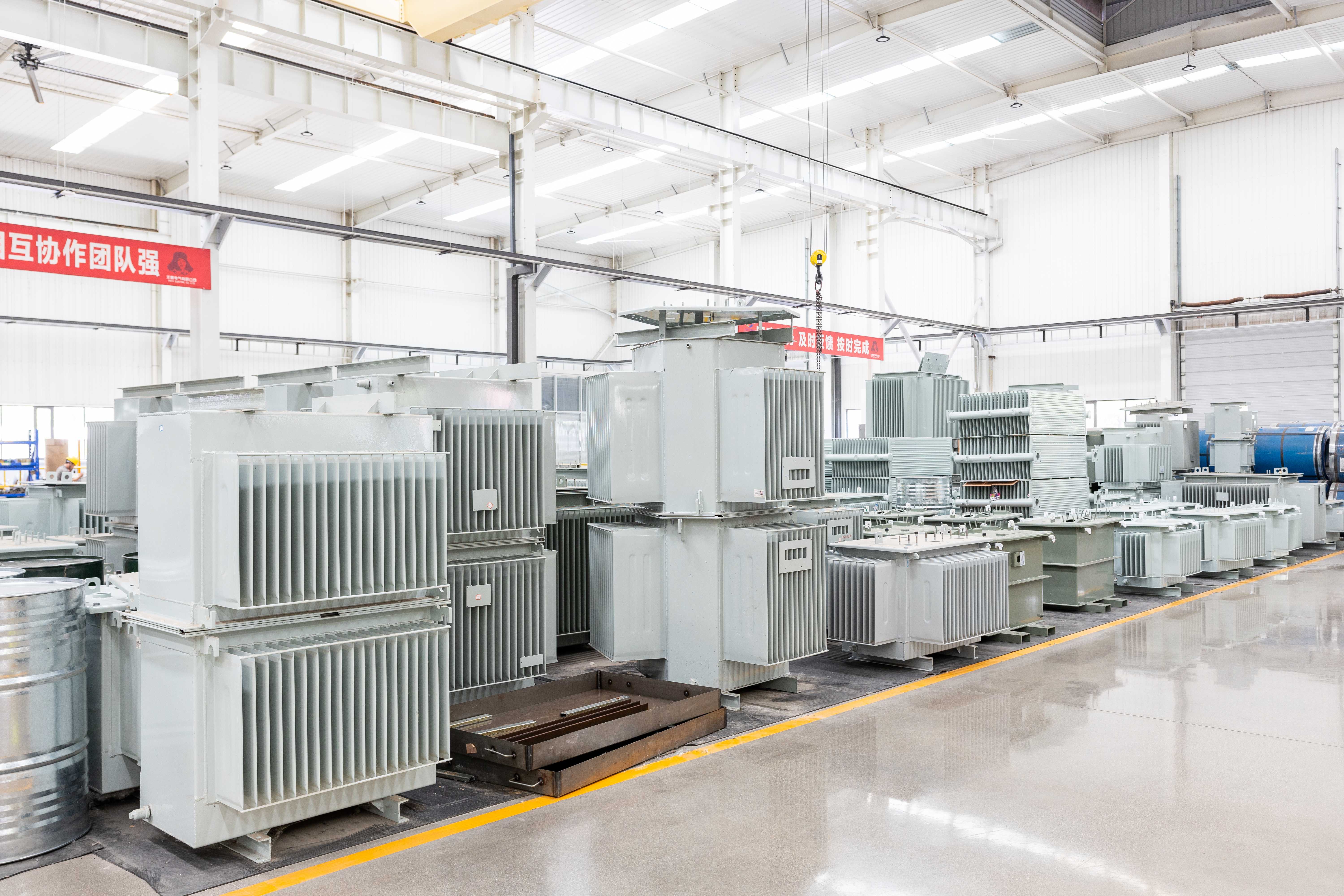
Customizable tank dimensions, mounting layouts, and optional casters simplify installation in space-constrained substations or retrofit projects.
No-load and load losses can be tailored to specific tariff structures or efficiency targets (e.g., S20/S22), optimizing lifecycle cost rather than relying on generic standards.
Factory-integrated WTI/OTI sensors with alarm contacts enable remote condition monitoring, reducing unplanned outages through predictive maintenance.
Choice of fully sealed enclosure or conservator-with-oil-pillow configuration aligns with local maintenance practices and environmental conditions.
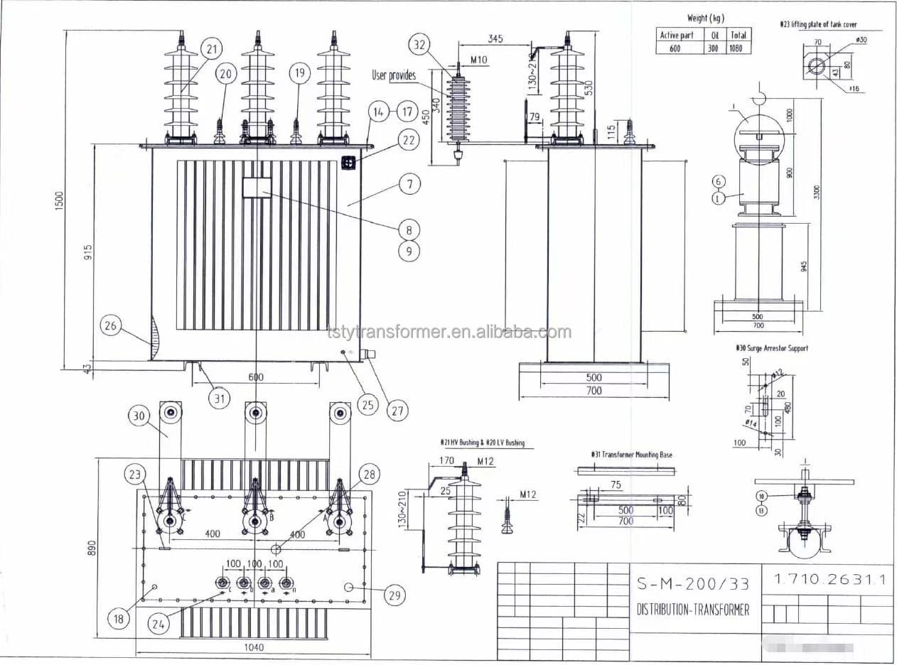
Dedicated team provides tailored design validation based on client-specific voltage ratios, tap ranges, and dimensional constraints, ensuring seamless integration into existing substations.
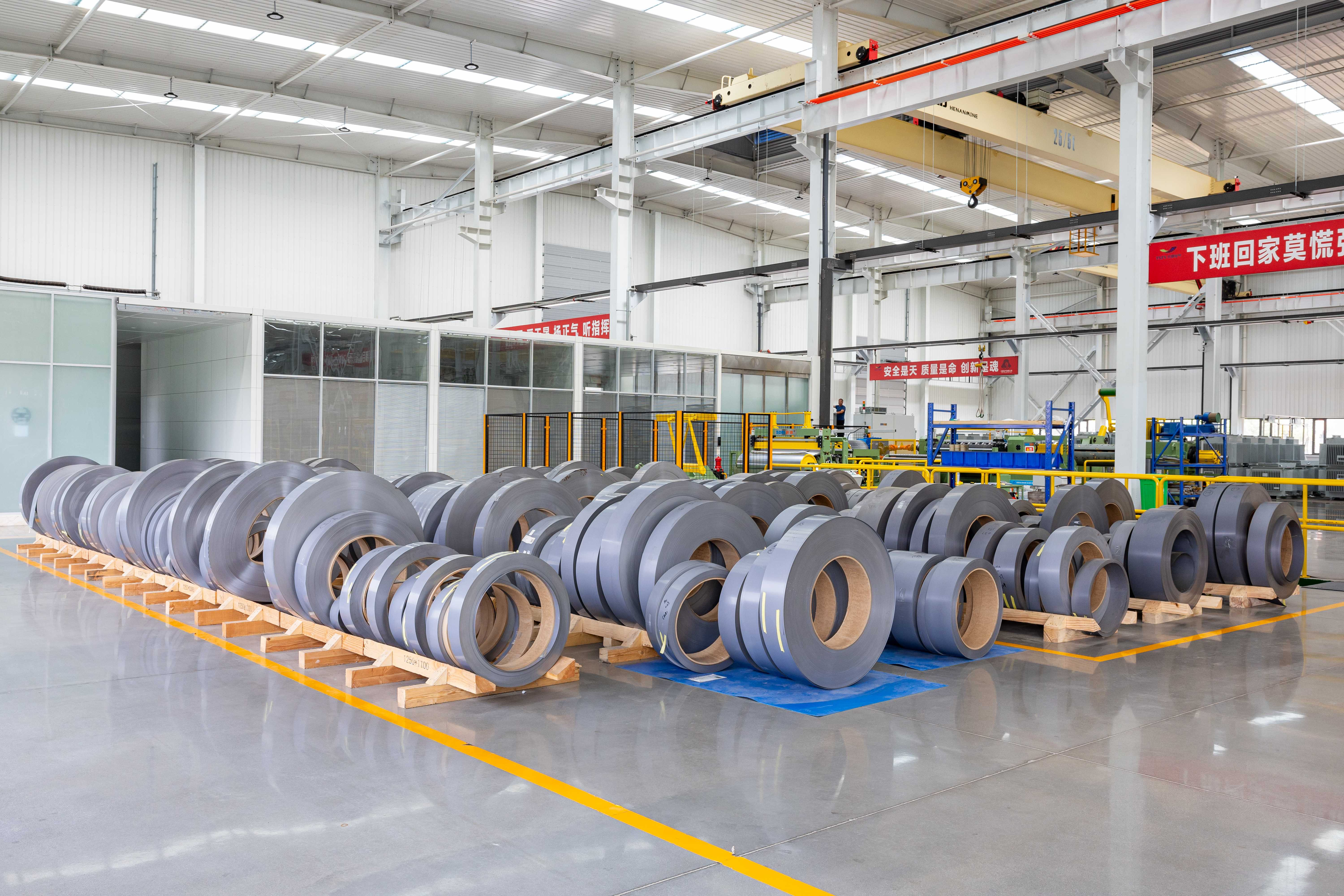
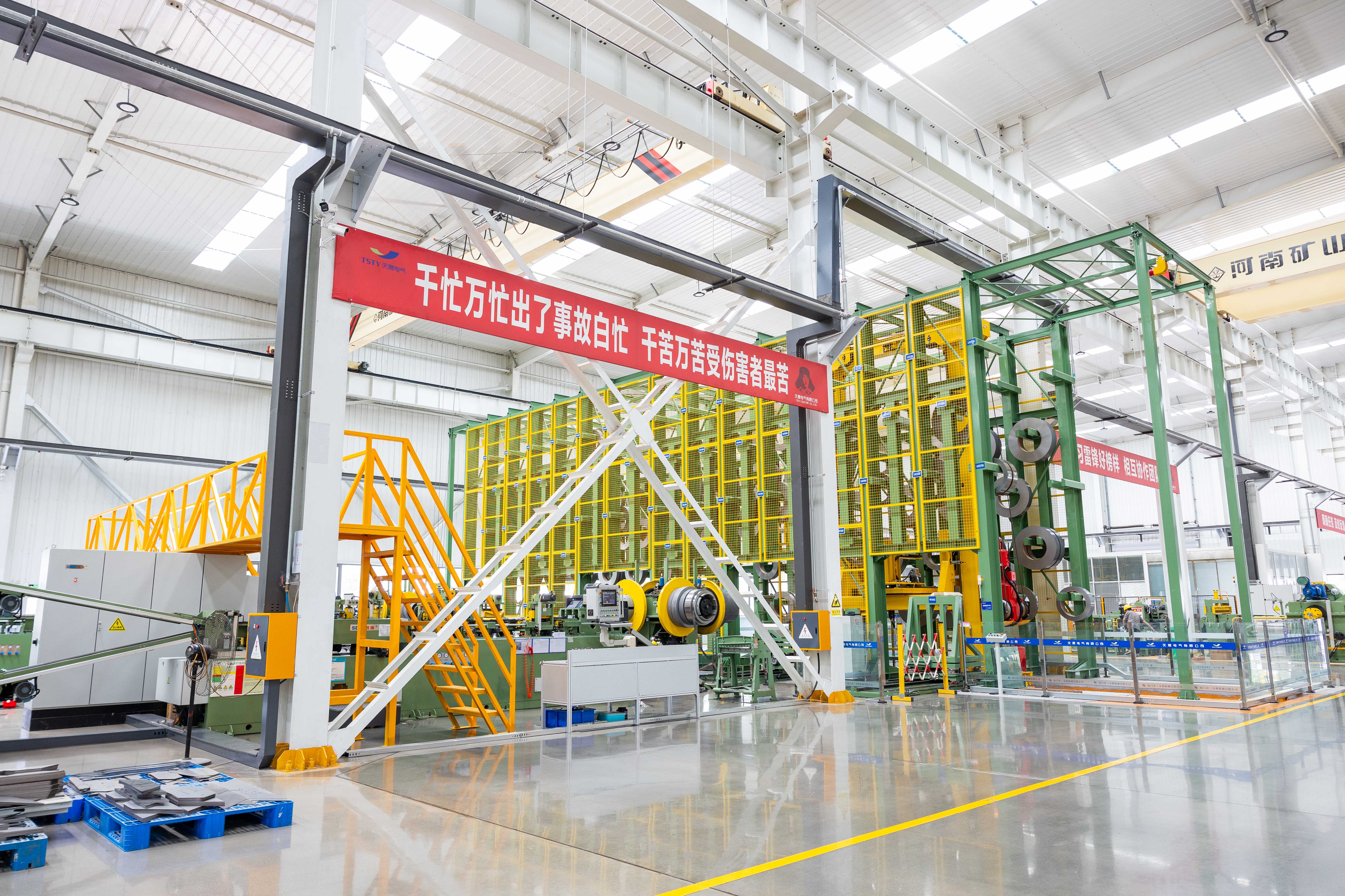
All core steel, copper conductors, and insulating oils are sourced from certified suppliers with full batch traceability; incoming materials undergo pre-production verification to prevent quality deviations.
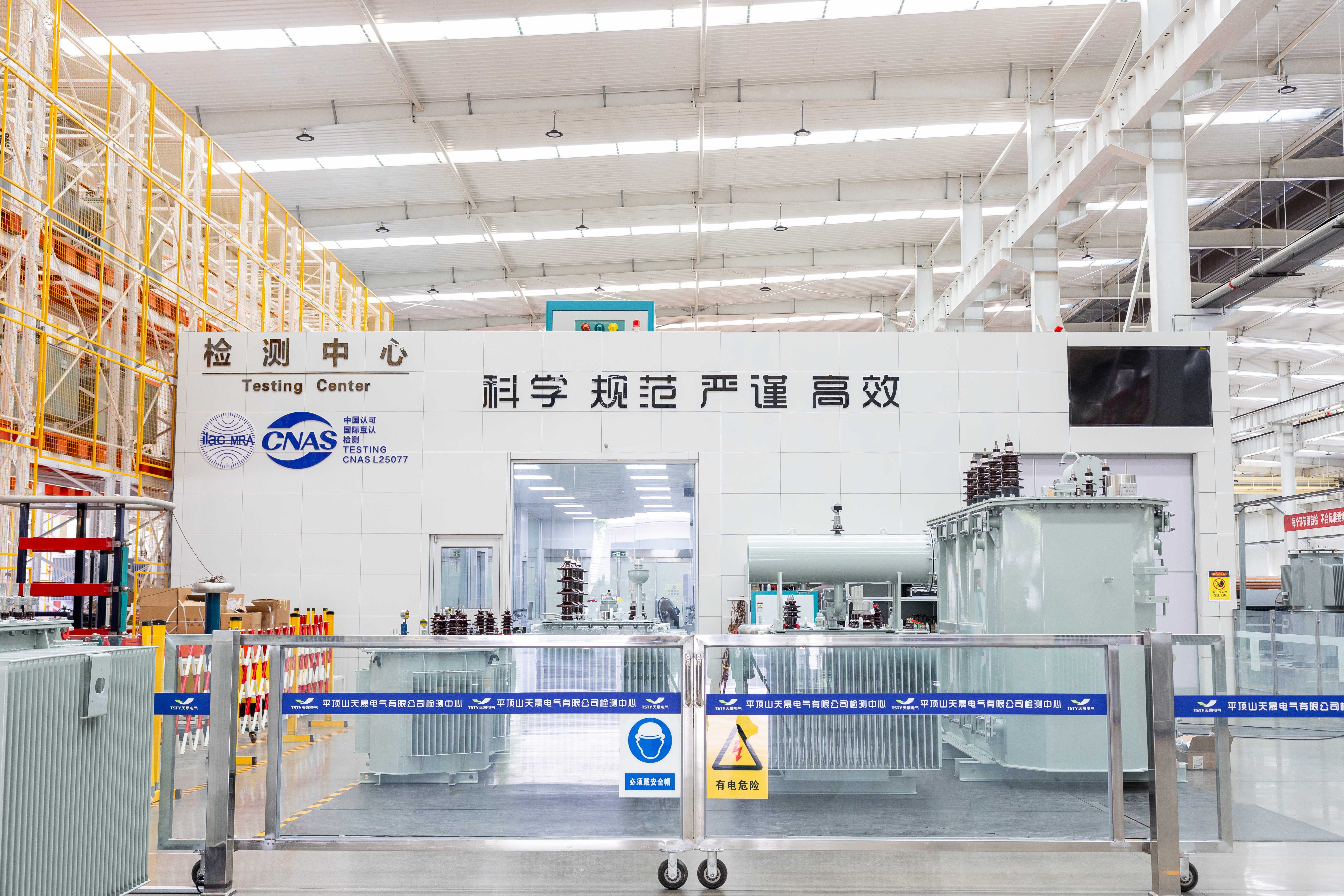
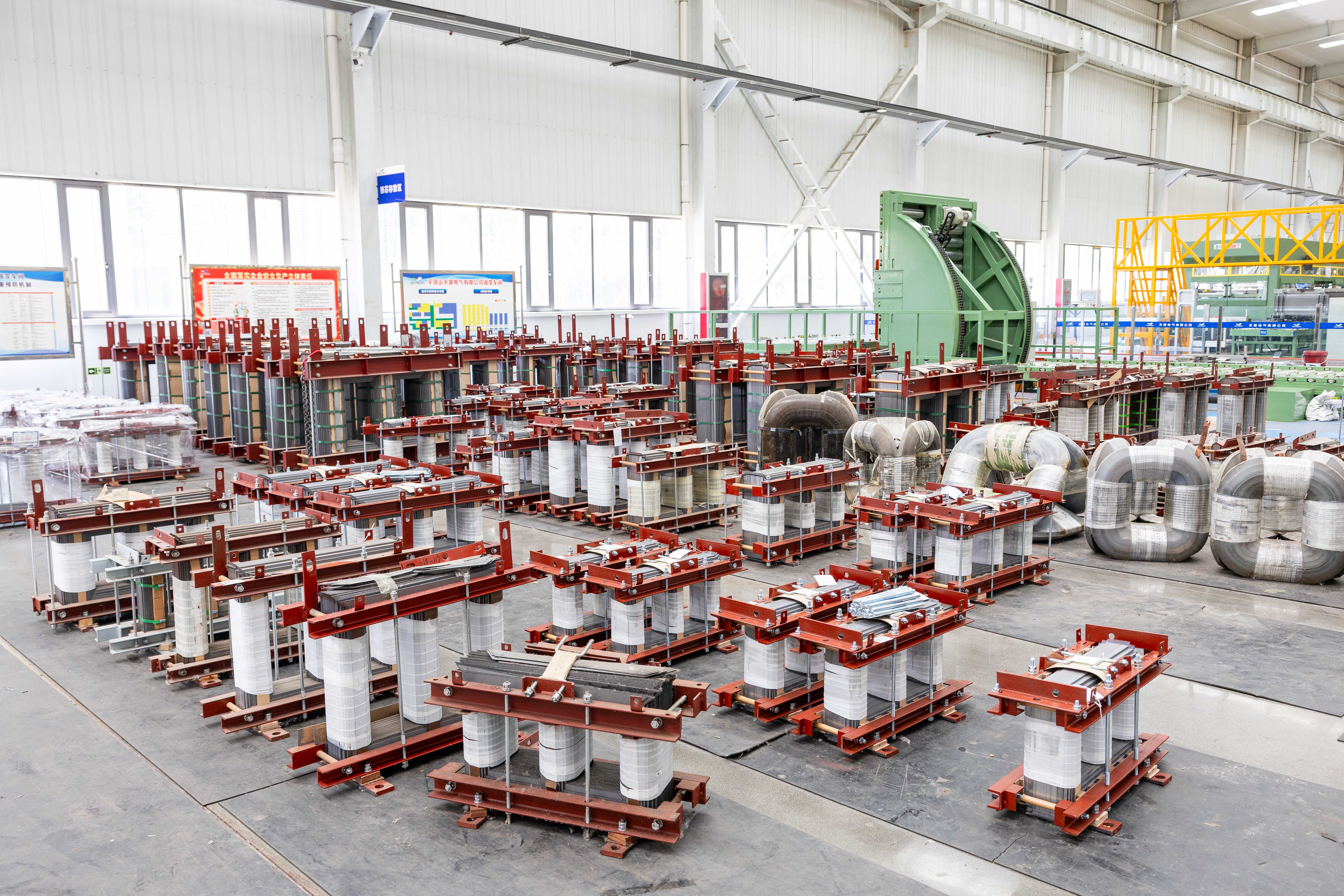
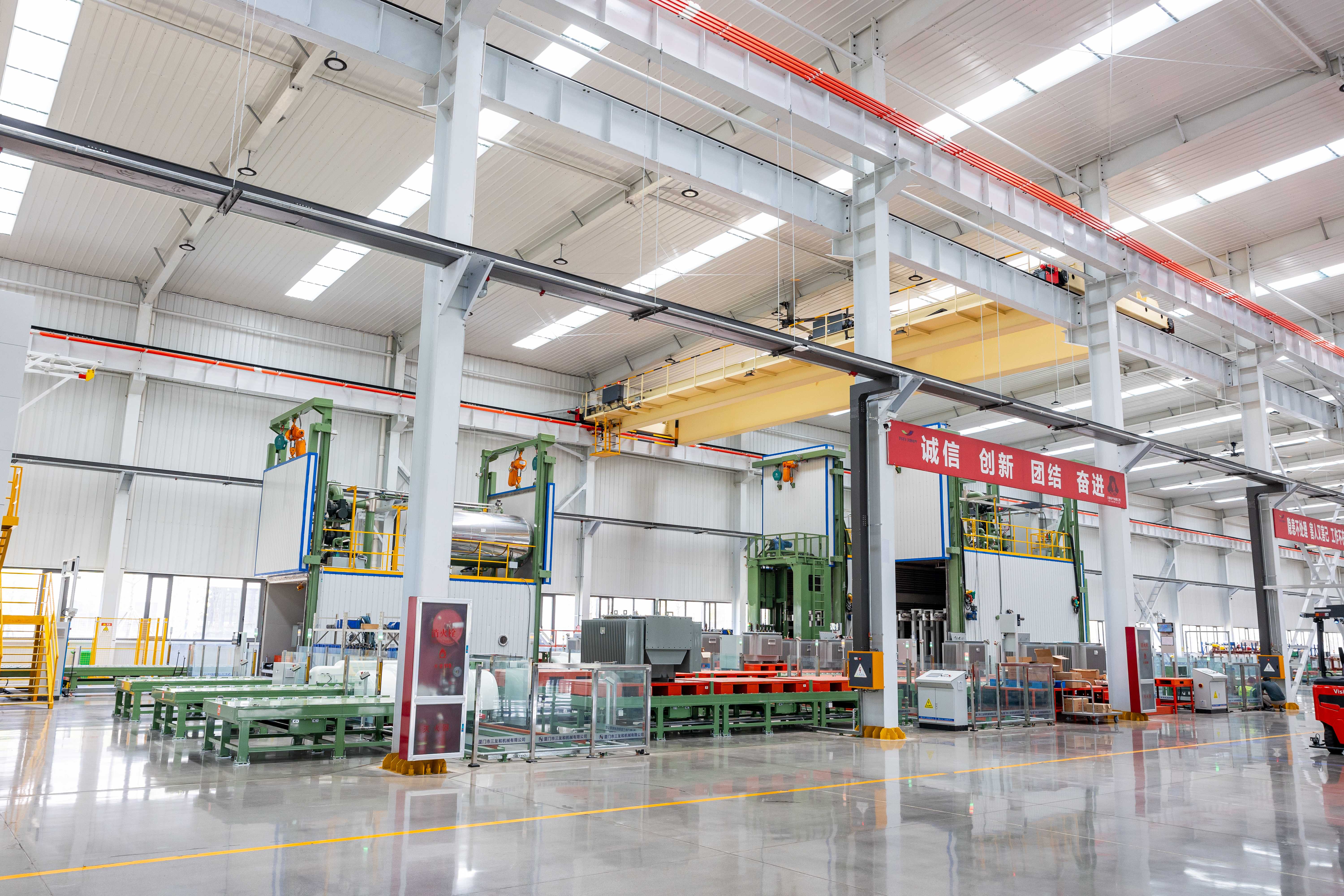
95% automated core stacking and winding processes eliminate human error; vacuum oil injection removes micro-bubbles to enhance dielectric strength without manual intervention.
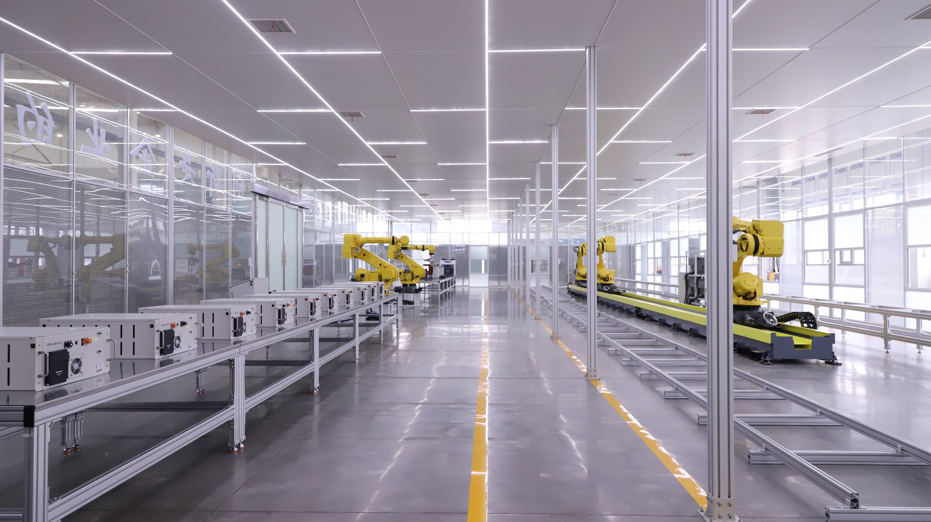
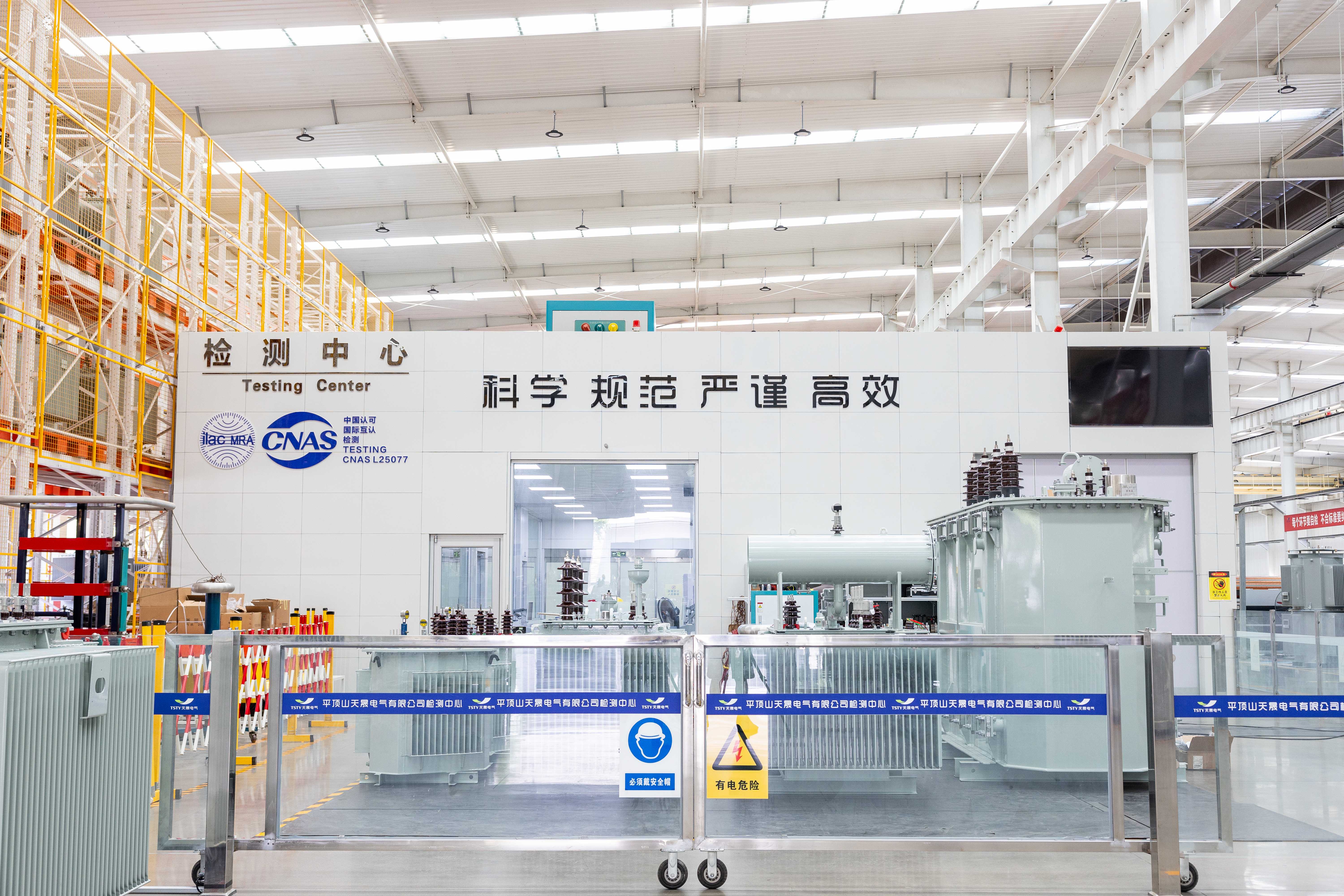
Every unit undergoes lightning impulse test, no-load/load loss measurement, insulation resistance verification, and ratio/tap position checks in our CNAS-accredited laboratory. All qualified products include globally recognized test reports aligned with IEC 60076 requirements.
|
Rated Capacity |
Voltage Combination |
Vector Group |
No-Load Loss(w) |
Load Loss |
No-Load Current (%) |
Short Circuit Impedance (%) |
||
|
High Voltage(kV) |
Tapping Range |
Low Voltage (kV) |
||||||
|
30 |
20 |
±5% ±2×2.5% |
0.4 |
Dyn11 Yyn0 |
90 |
690 |
2.1 |
5.5 |
|
50 |
130 |
1010 |
2 |
|||||
|
63 |
150 |
1200 |
1.9 |
|||||
|
80 |
180 |
1440 |
1.8 |
|||||
|
100 |
200 |
1730 |
1.6 |
|||||
|
125 |
240 |
2080 |
1.5 |
|||||
|
160 |
290 |
2540 |
1.4 |
|||||
|
200 |
340 |
3000 |
1.3 |
|||||
|
250 |
400 |
3520 |
1.2 |
|||||
|
315 |
480 |
4210 |
1.1 |
|||||
|
400 |
570 |
4970 |
1 |
|||||
|
500 |
680 |
5940 |
1 |
|||||
|
630 |
810 |
6820 |
0.9 |
6 |
||||
|
800 |
980 |
8250 |
0.8 |
|||||
|
1000 |
1150 |
11330 |
0.7 |
|||||
|
1250 |
1380 |
13200 |
0.7 |
|||||
|
1600 |
1660 |
15950 |
0.6 |
|||||
|
2000 |
1950 |
19140 |
0.6 |
|||||
|
2500 |
2340 |
22200 |
0.5 |
|||||

Galvanized steel (standard) or stainless steel; custom color available.
With or without oil pillow—select based on maintenance strategy.

Off-circuit (standard) or on-load tap changer (OLTC) for uninterrupted regulation; custom tap positions available.

Fully sealed enclosure for maintenance-free operation; optional casters for easy on-site positioning.
Winding Temperature Indicator (WTI), Oil Temperature Indicator (OTI)—with alarm contacts if needed.
No-load and load losses customizable to meet specific efficiency targets (e.g., S20, S22).
Overall size and mounting layout adjustable; nameplate customizable in English or local language.


Tell us your project requirements—voltage level, environment, grid code, or delivery timeline—and we’ll provide a compliant, optimized solution.





 EN