
Integrated on-load tap changer ensures uninterrupted power quality and grid stability for critical infrastructure.
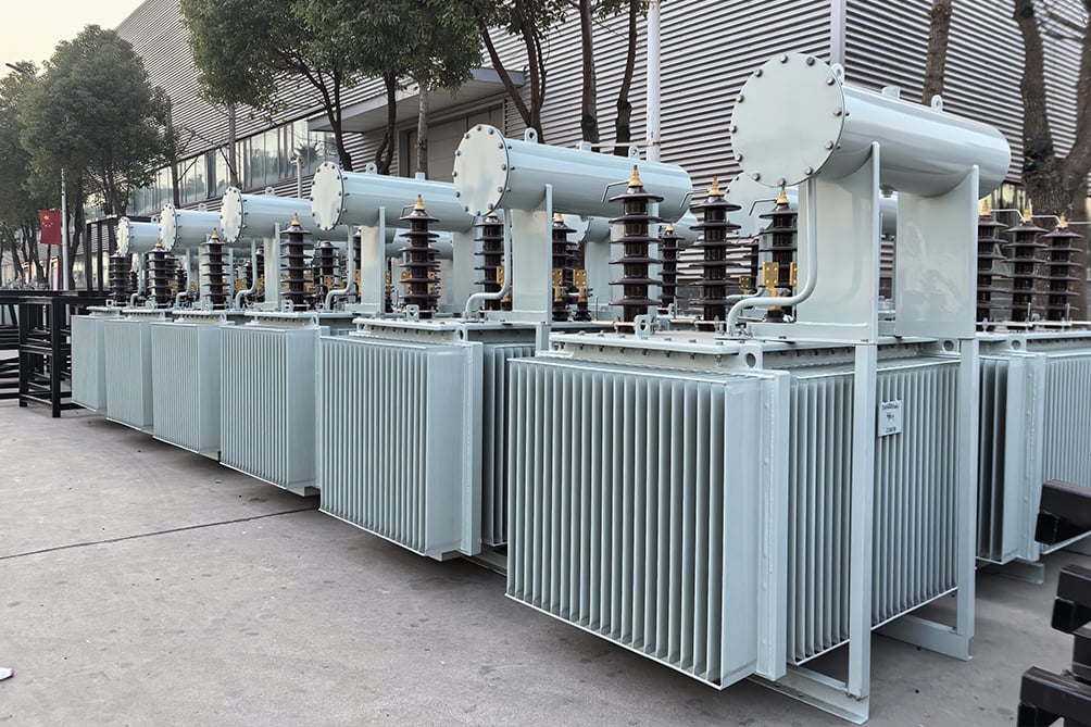
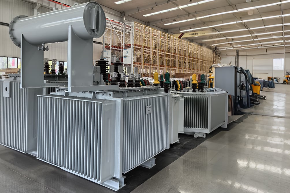
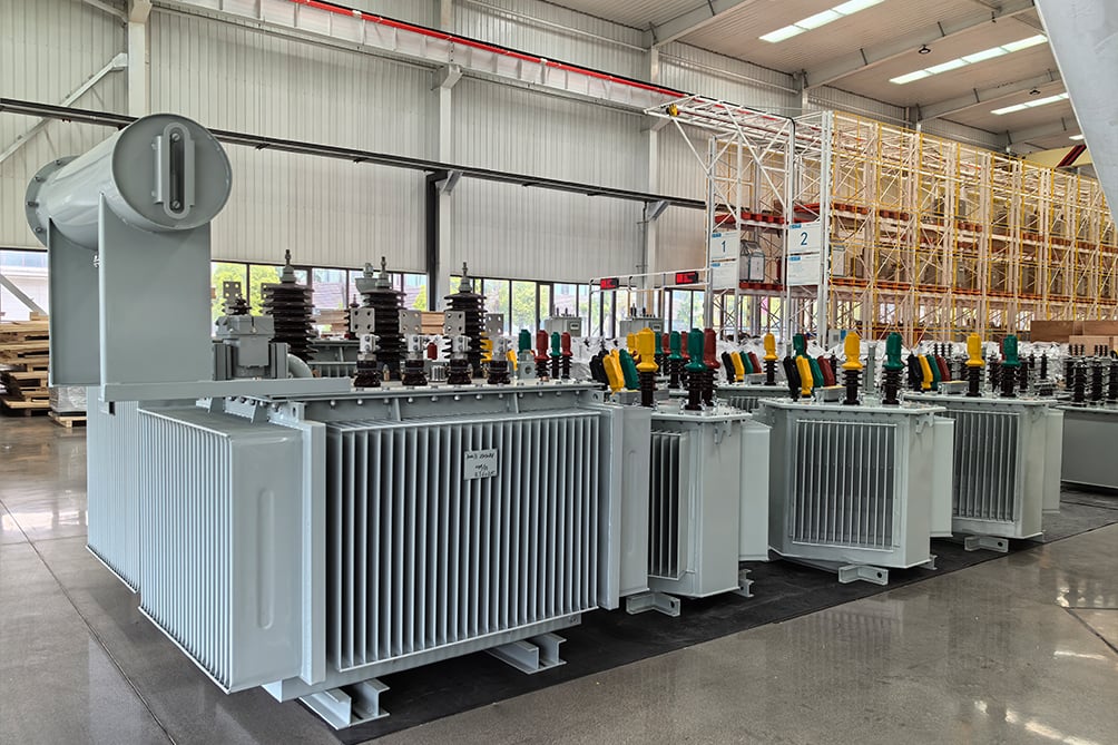
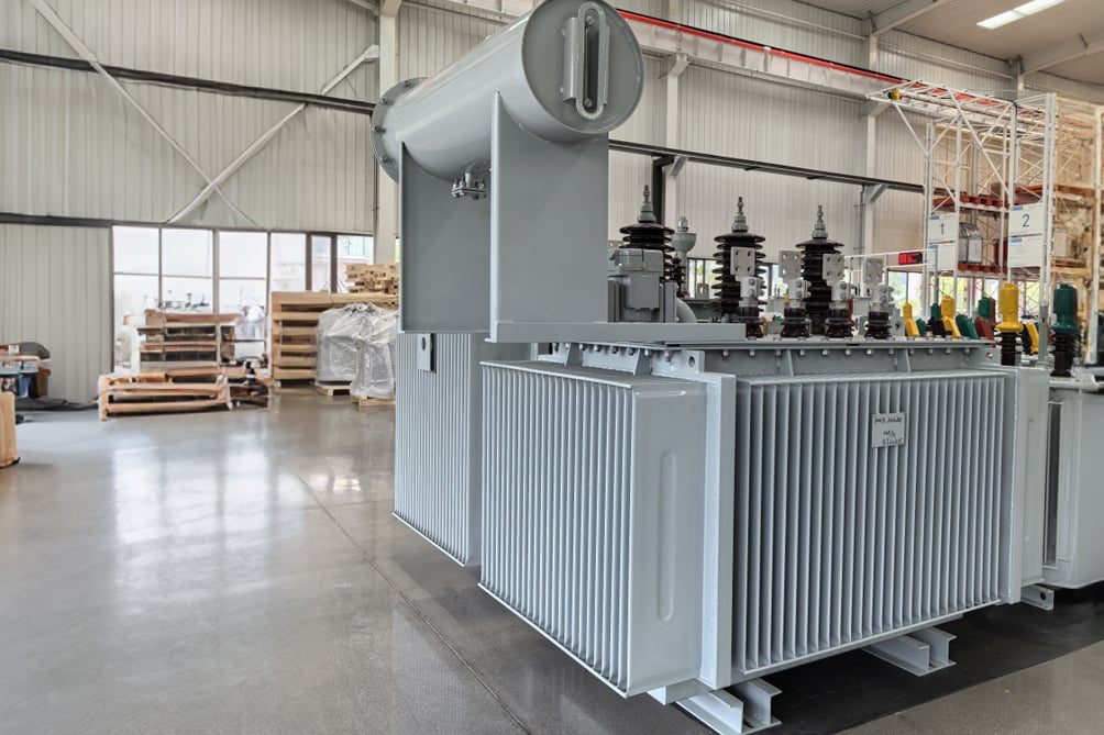
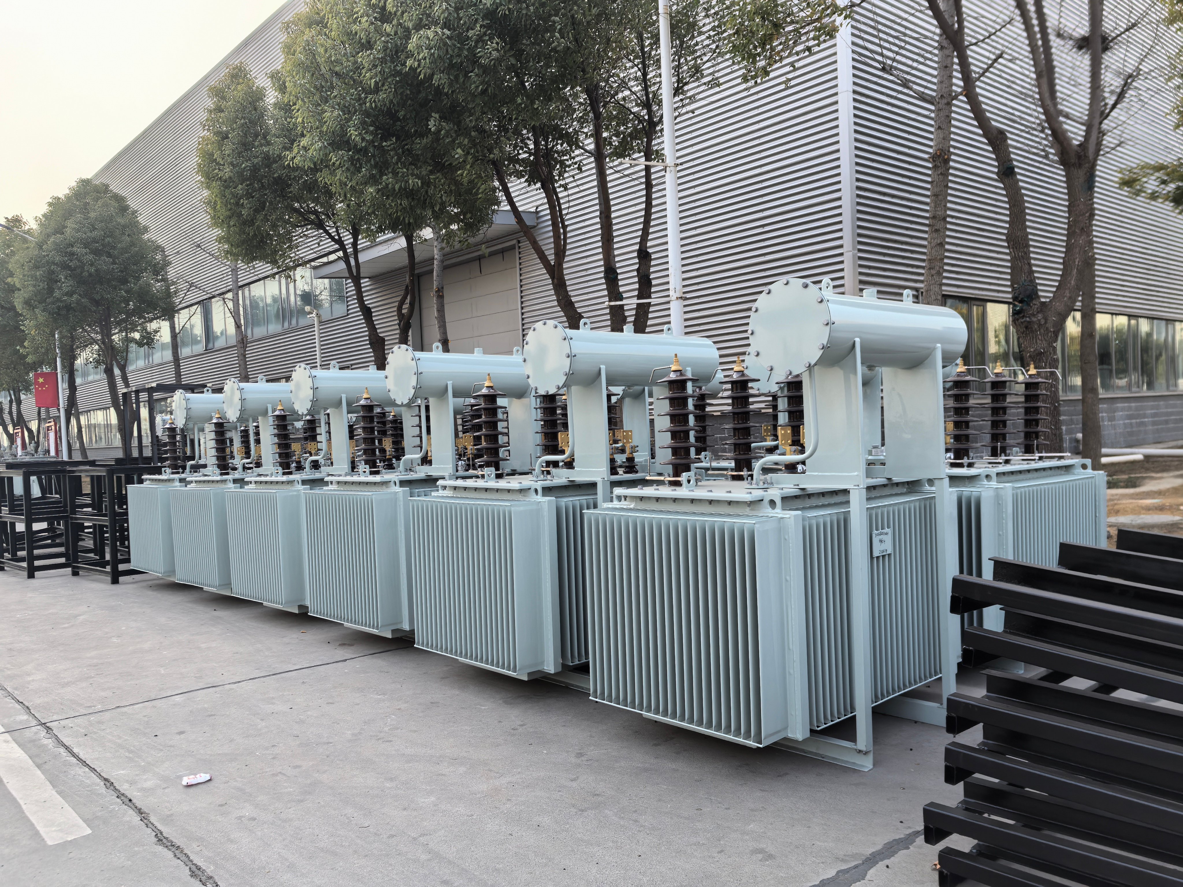




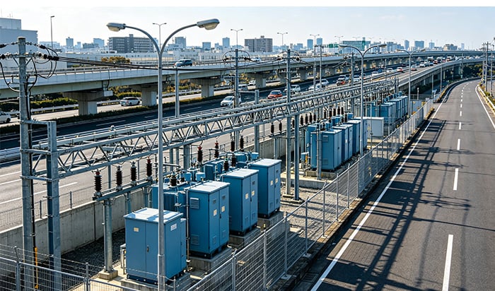

OLTC mechanism adjusts taps under full load without de-energizing the transformer, eliminating planned outages for voltage correction and maintaining 99.99% supply continuity for critical loads.
Real-time tap switching compensates for load-induced voltage drops and renewable generation swings, keeping downstream voltage within equipment tolerance bands and preventing nuisance tripping or process disruptions.
Built-in position feedback and motor drive interface enable closed-loop control with automatic voltage regulators (AVR), supporting remote setpoint adjustment, event logging, and predictive maintenance alerts.
Sustained voltage within ±0.5% reduces thermal stress on motors, drives, and electronic loads, decreasing premature failure rates and lowering total cost of ownership for connected assets.
Vacuum-type or resistor-transition tap changers rated for 300,000+ operations with maintenance intervals aligned to utility inspection cycles, minimizing lifecycle servicing costs versus conventional air-insulated designs.
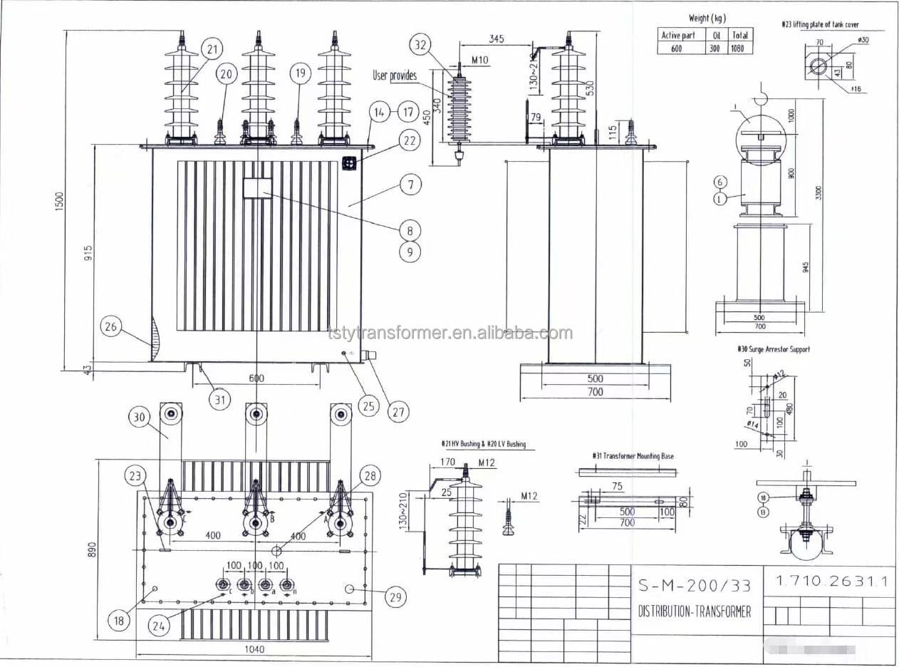
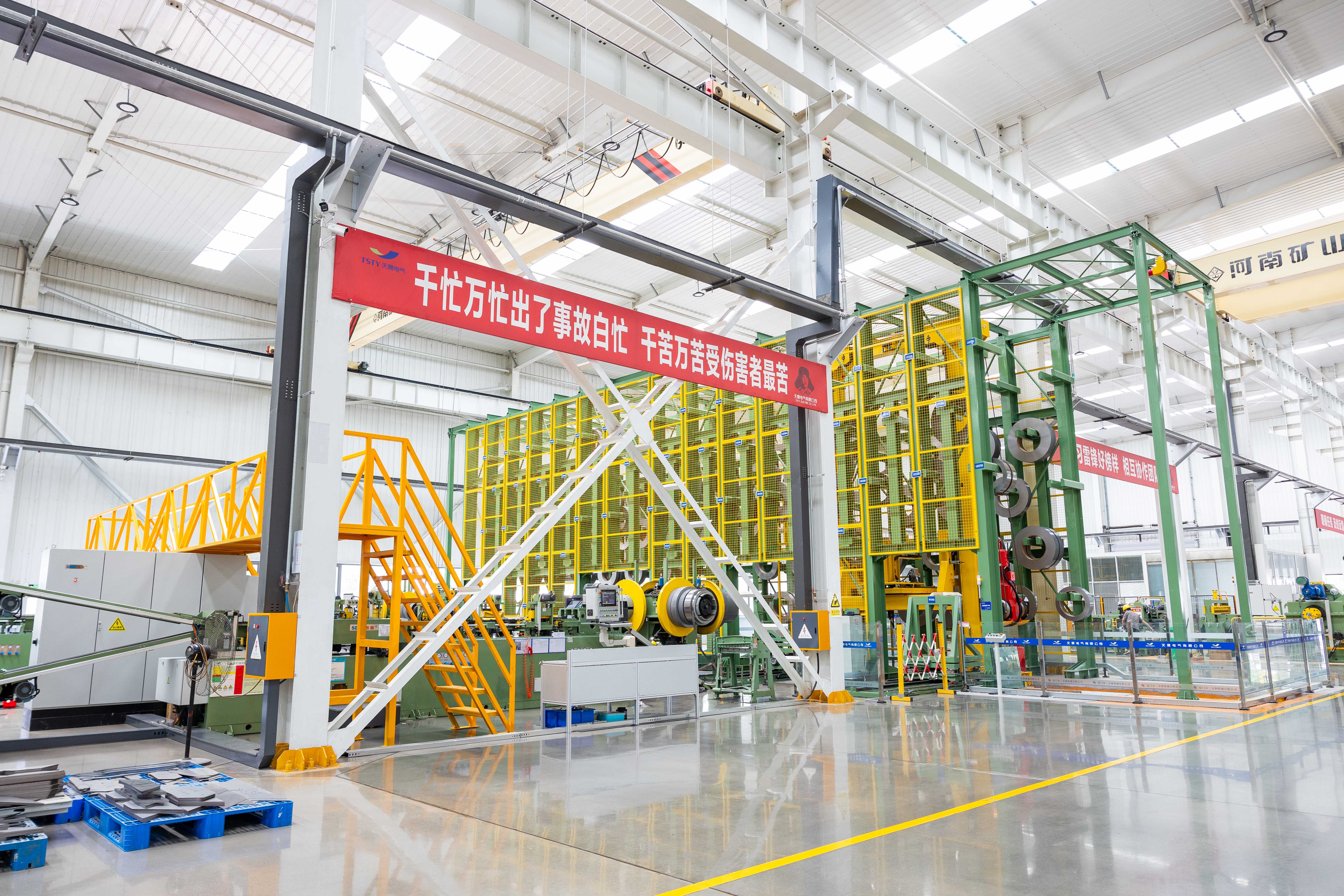
Each tap changer undergoes type testing per IEC 60214 including mechanical endurance, dielectric withstand, and transition impedance verification; production units receive routine operation tests to confirm alignment with rated cycle life.
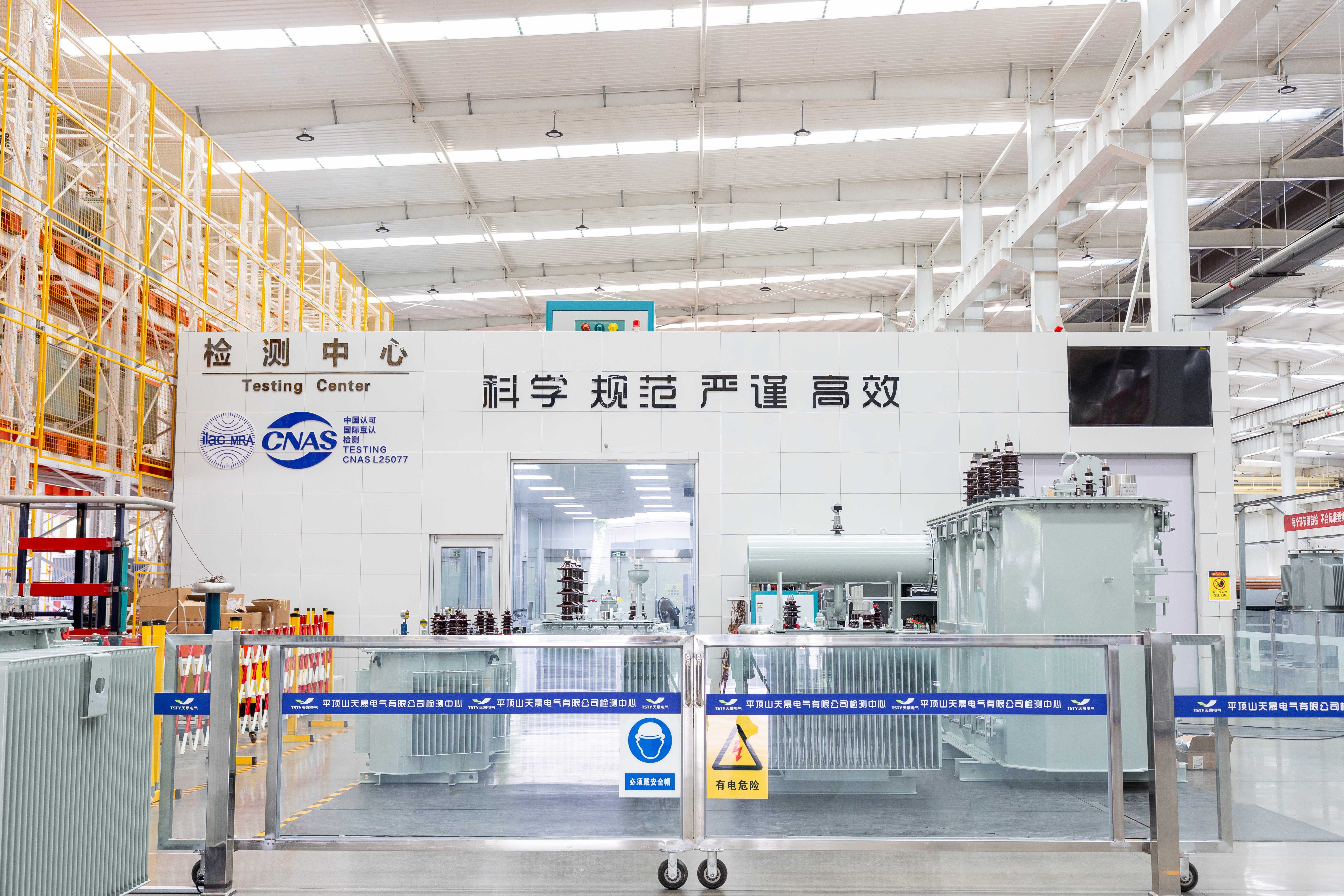
Tap step voltage and regulation range measured under load to confirm ±0.5% output tolerance across all positions; test reports include actual winding resistance and turns ratio data for traceability.
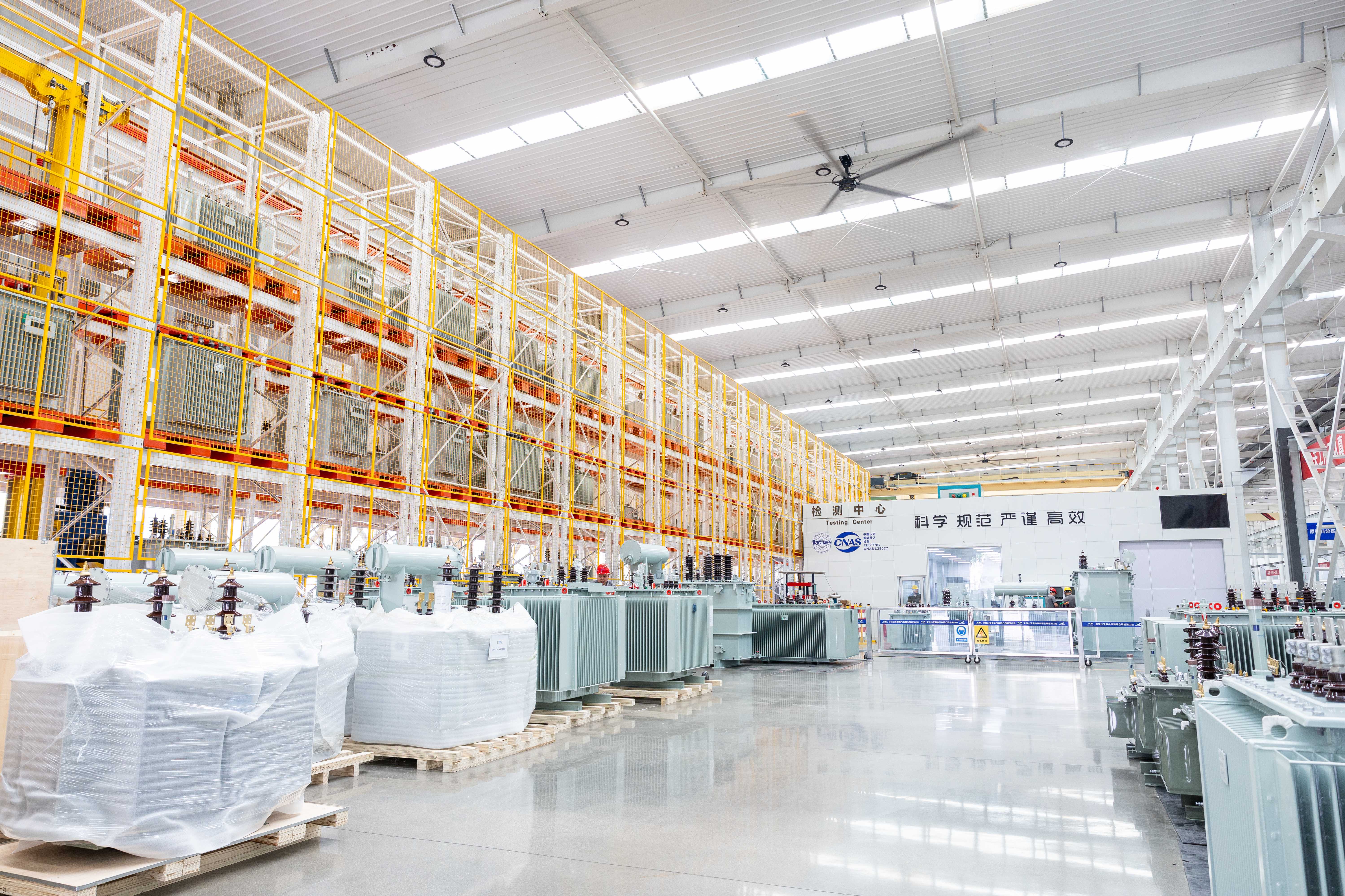
AVR interface validated with major SCADA protocols (IEC 61850, DNP3, Modbus) before shipment, ensuring plug-and-play integration with existing grid automation infrastructure without field reprogramming.
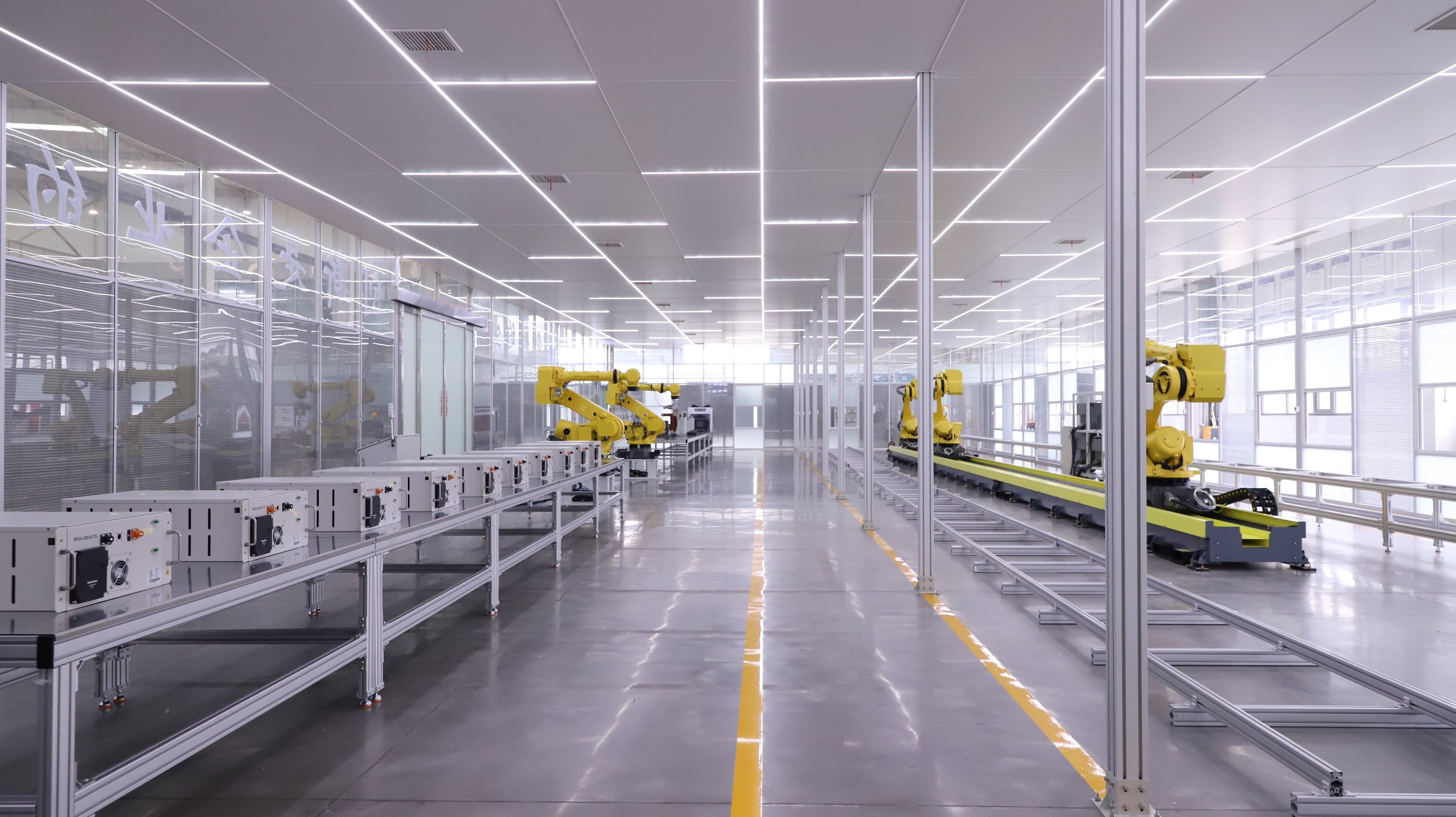
Electromagnetic transient analysis verifies tap-switching behavior under fault conditions and load rejection scenarios, confirming no overvoltage or instability during extreme grid events.
|
Voltage combination |
No-load current (%) |
Short -circuit impedance (%) |
||||||
|
Rated capacity (kVA) |
HV (kV) |
HV tapping range (%) |
LV (kV) |
Connection symbol |
No-load loss (W) |
Load loss (W) |
||
|
160(50) |
10 10.5 11 |
+/-5 |
0.4 |
Dyn11 Yyn0 |
400(170) |
2585(870) |
1.6(0.9) |
4.0 (4.0) |
|
200(63) |
480(200) |
3060(1040) |
1.5(0.9) |
|||||
|
250(80) |
560(250) |
3600(1250) |
1.4(0.7) |
|||||
|
315(100) |
670(290) |
4320(1500) |
1.4(0.7) |
|||||
|
400(125) |
800(340) |
5220(1800) |
1.3(0.6) |
4.5 (4.0) |
||||
|
500(160) |
960(400) |
6210(2200) |
1.2(0.6) |
|||||
|
630(200) |
1200(470) |
7650(2600) |
1.1(0.5) |
|||||

Vacuum-type for high-frequency operation (>50 ops/day) in data centers/renewable stations, or resistor-transition for industrial base-load applications; tap range, step voltage, and position count fully customizable to match local grid code and AVR requirements.
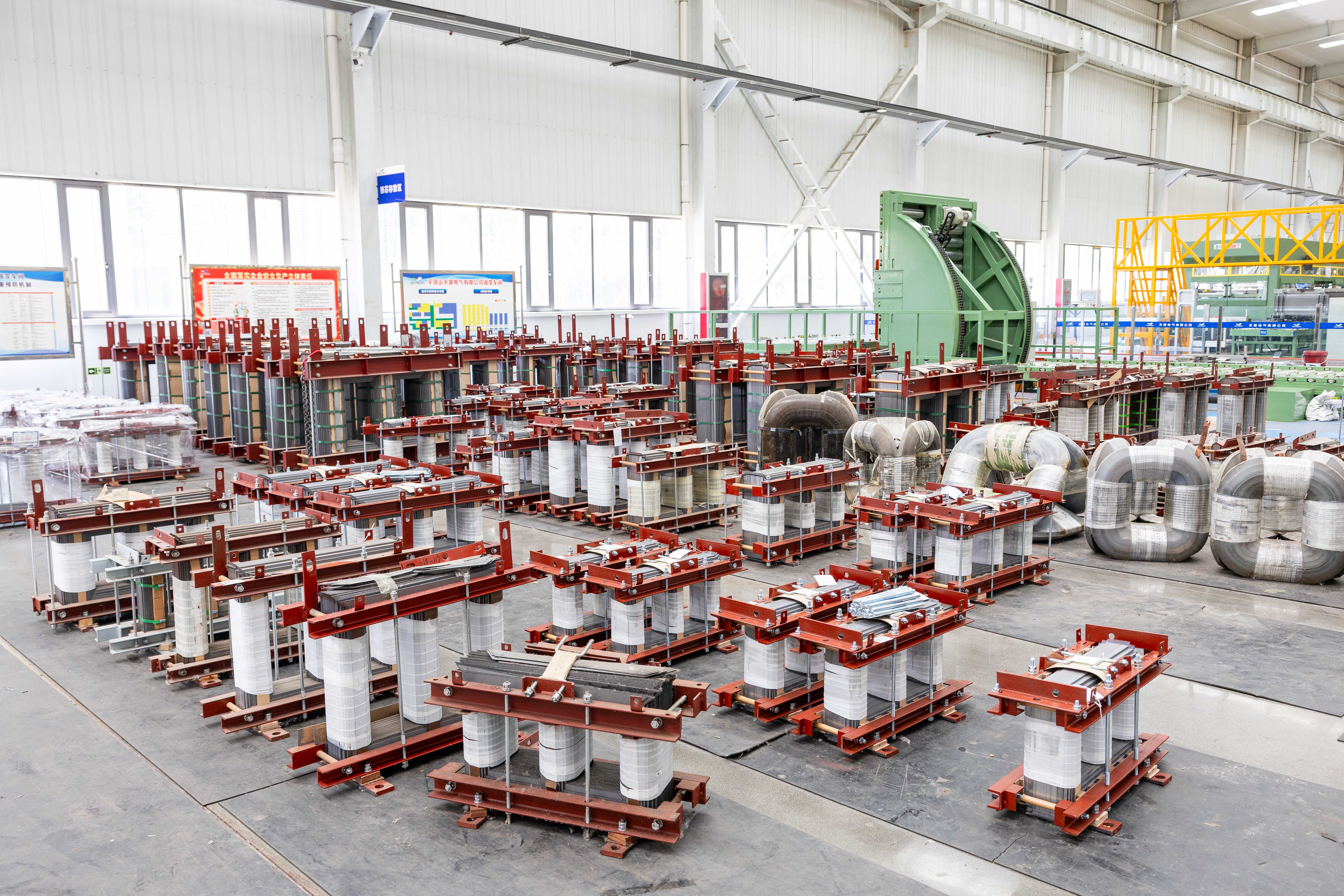
OLTC-specific sensors including position encoder, motor current monitor, contact wear indicator, and switching arc counter with digital outputs for predictive maintenance; optional WTI/OTI and DGA sensors integrated into unified asset health platform.

Factory-prewired terminal blocks for IEC 61850, DNP3, or Modbus communication; optional redundant control power supply and manual override panel for fail-safe operation during communication loss.

Carbon steel with hot-dip galvanizing for standard outdoor use, or stainless steel for coastal/industrial corrosion environments; sealed-tank design for reduced maintenance or conservator with nitrogen blanket for high-altitude/humid sites.
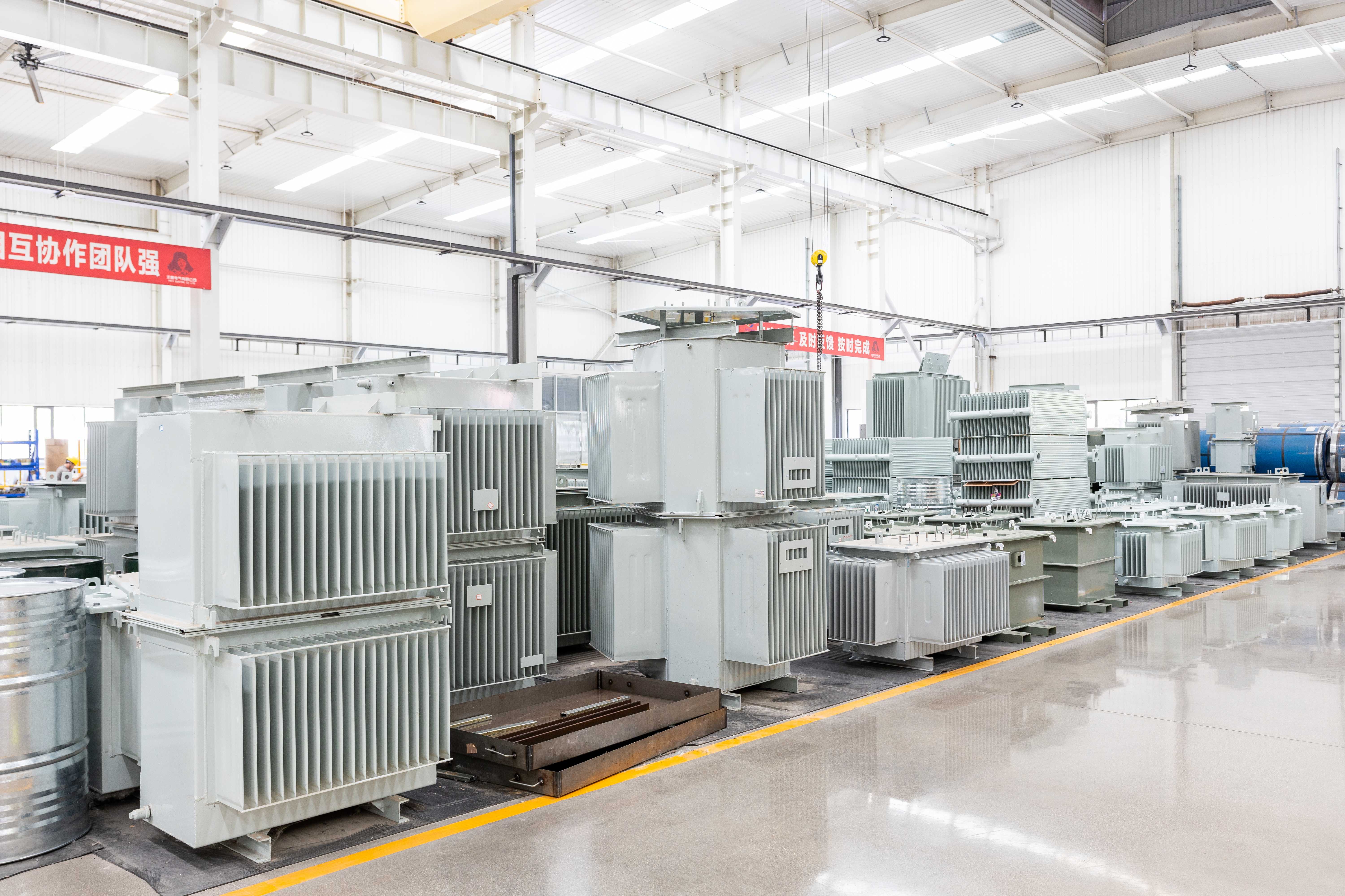
Compact OLTC compartment design reduces overall footprint vs. conventional units; optional heavy-duty casters, jacking pads, and low-profile bushing arrangements for indoor/substation retrofit projects with space constraints.
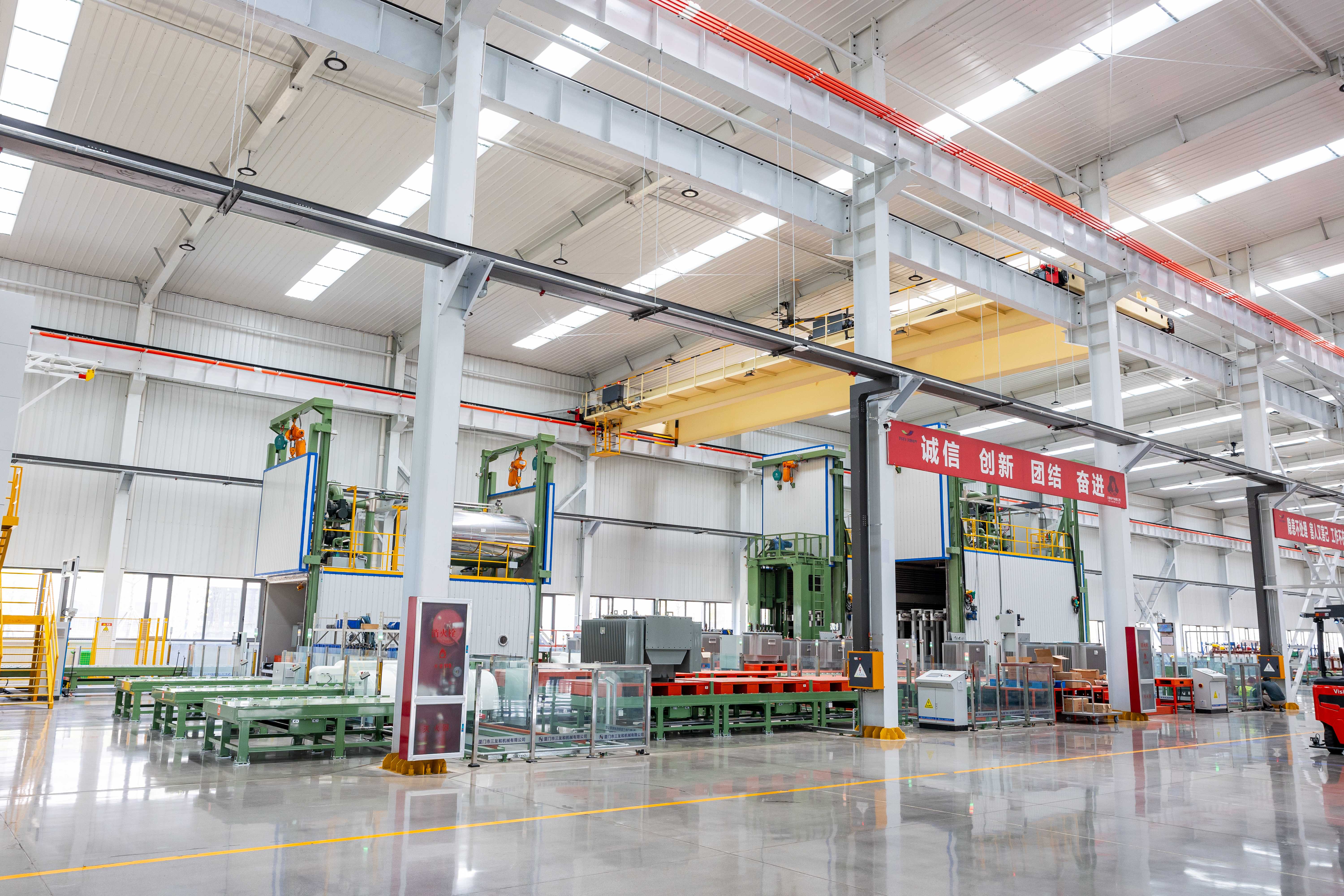
No-load and load losses optimized for project-specific efficiency targets while maintaining dynamic regulation capability; custom nameplates with QR codes linking to OLTC maintenance manuals, spare parts lists, and commissioning checklists.
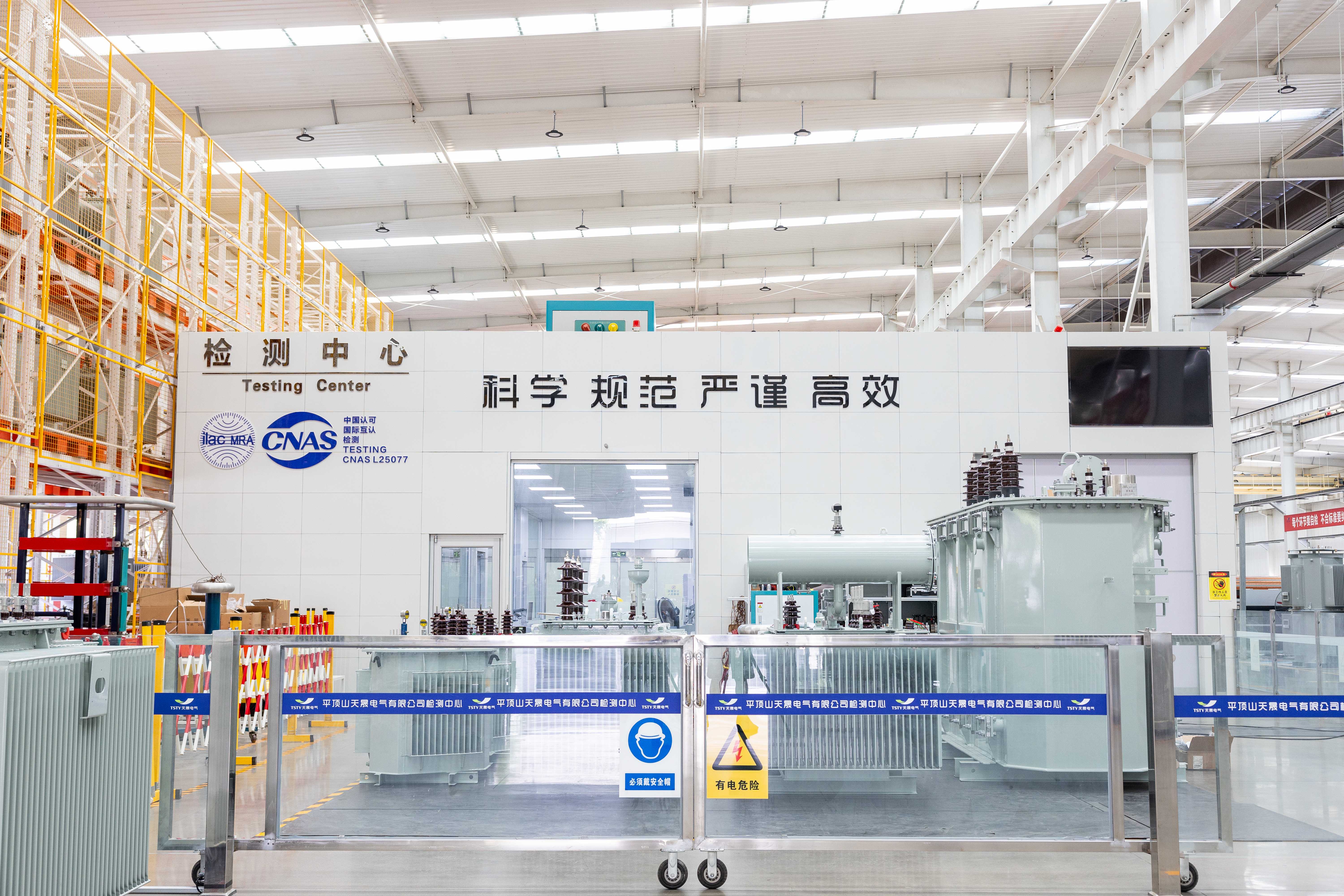
Factory-calibrated circulating current compensation and tap position synchronization for multi-unit OLTC installations; optional master-slave control modules and load-sharing relays to prevent unequal loading during simultaneous voltage regulation.


Tell us your project requirements—voltage level, environment, grid code, or delivery timeline—and we’ll provide a compliant, optimized solution.





 EN