
High-capacity, IEC/GOST certified oil-immersed transformer for 63/66kV sub-transmission and heavy industrial power supply
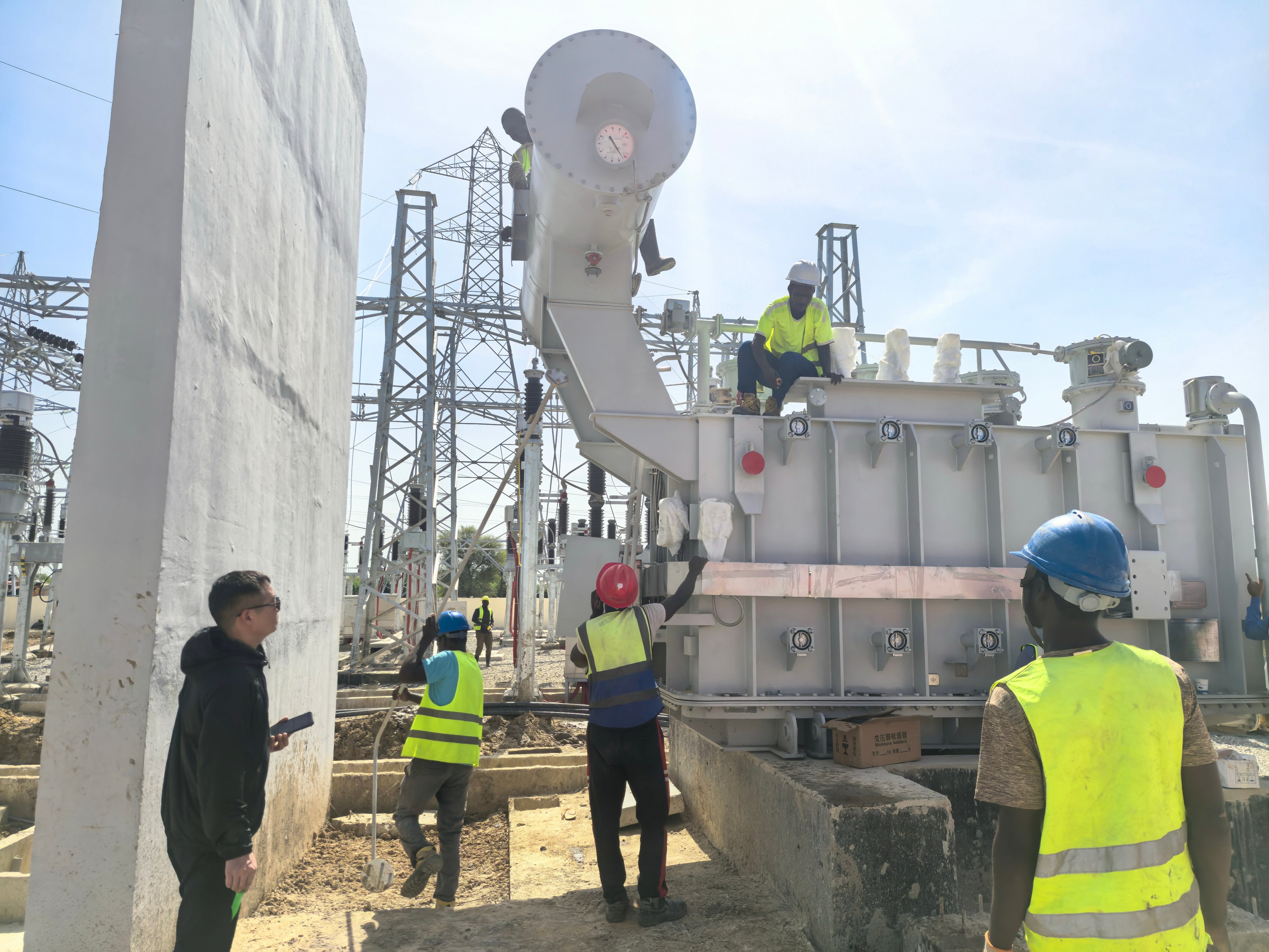
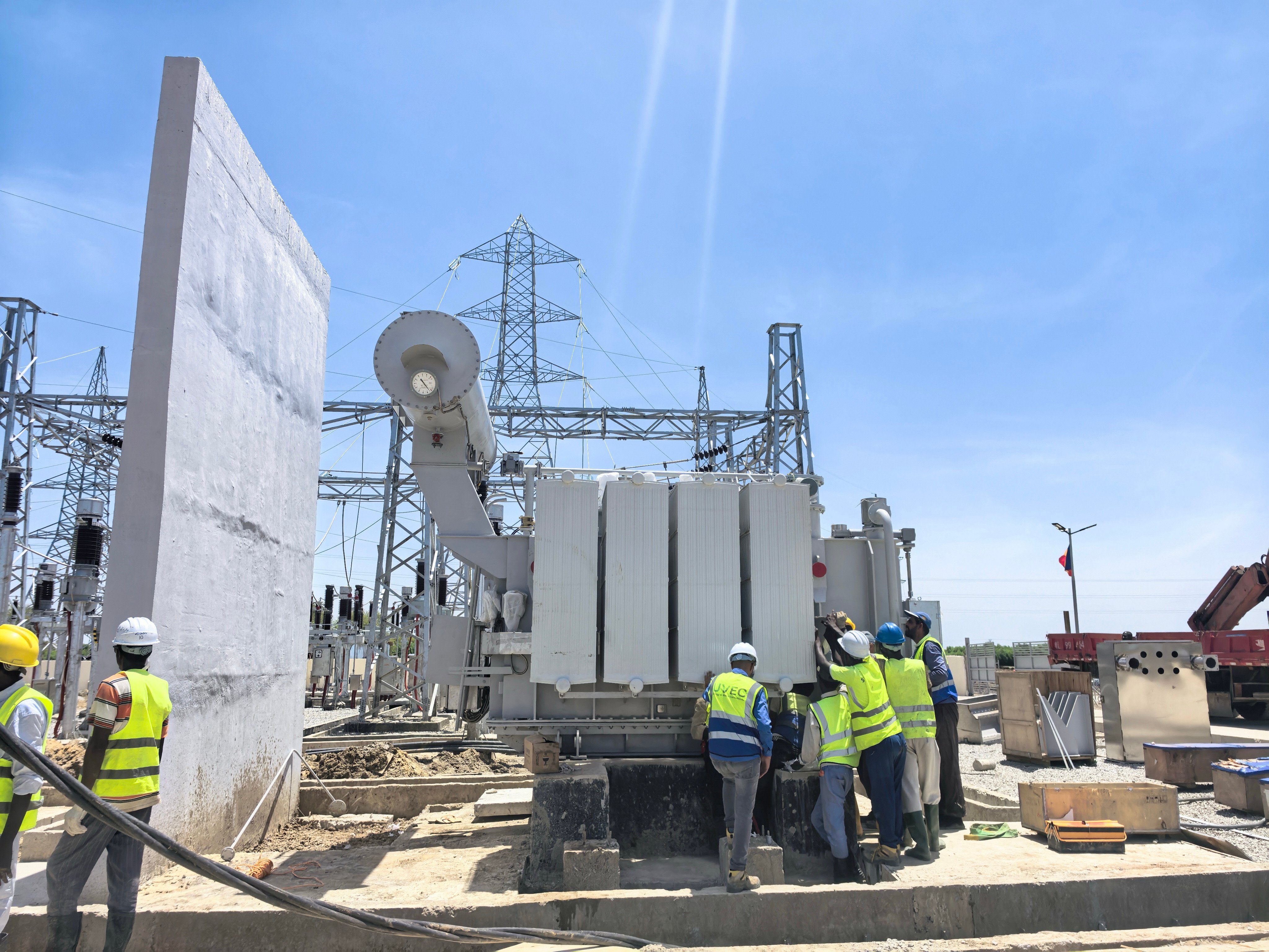
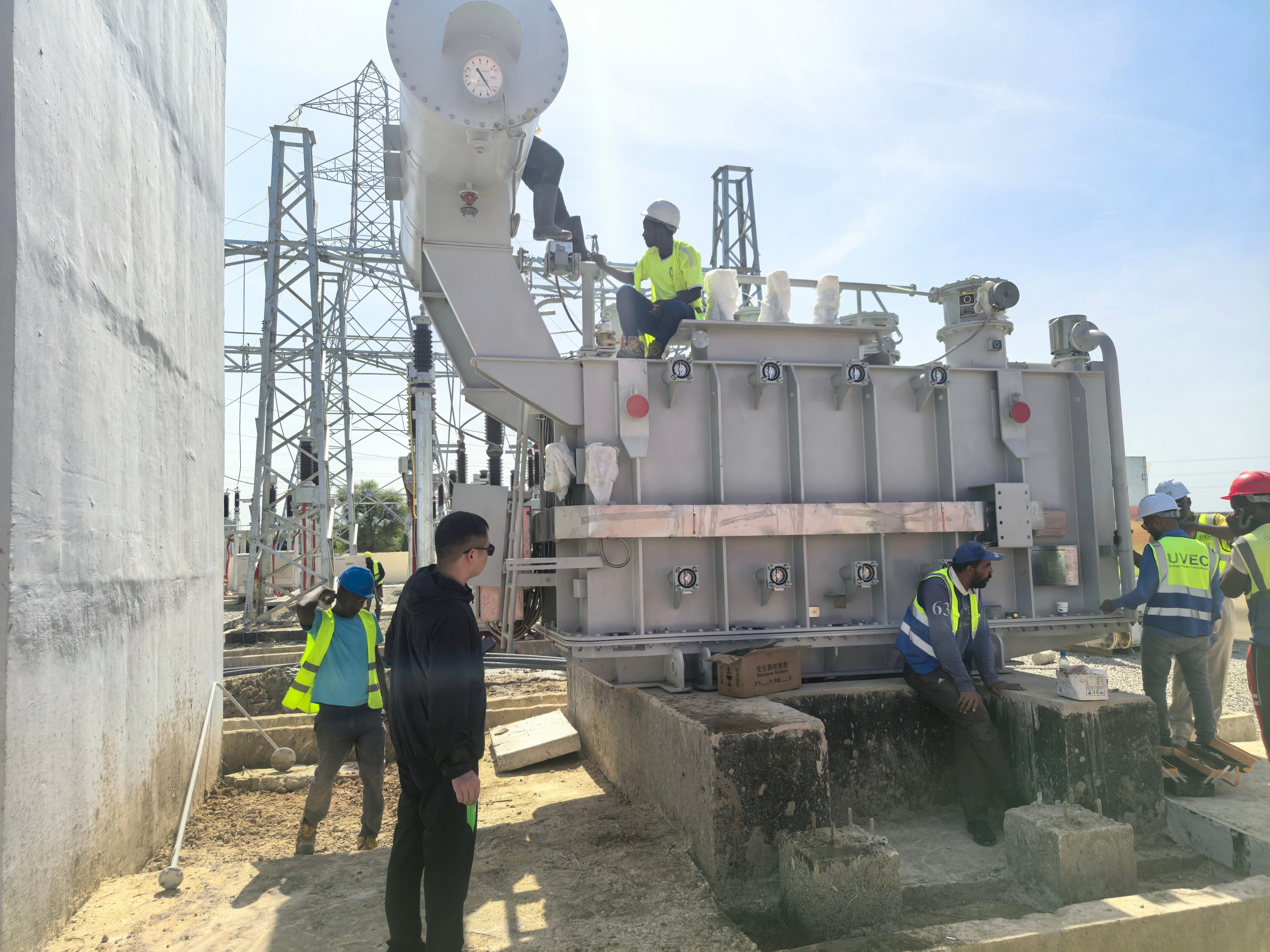
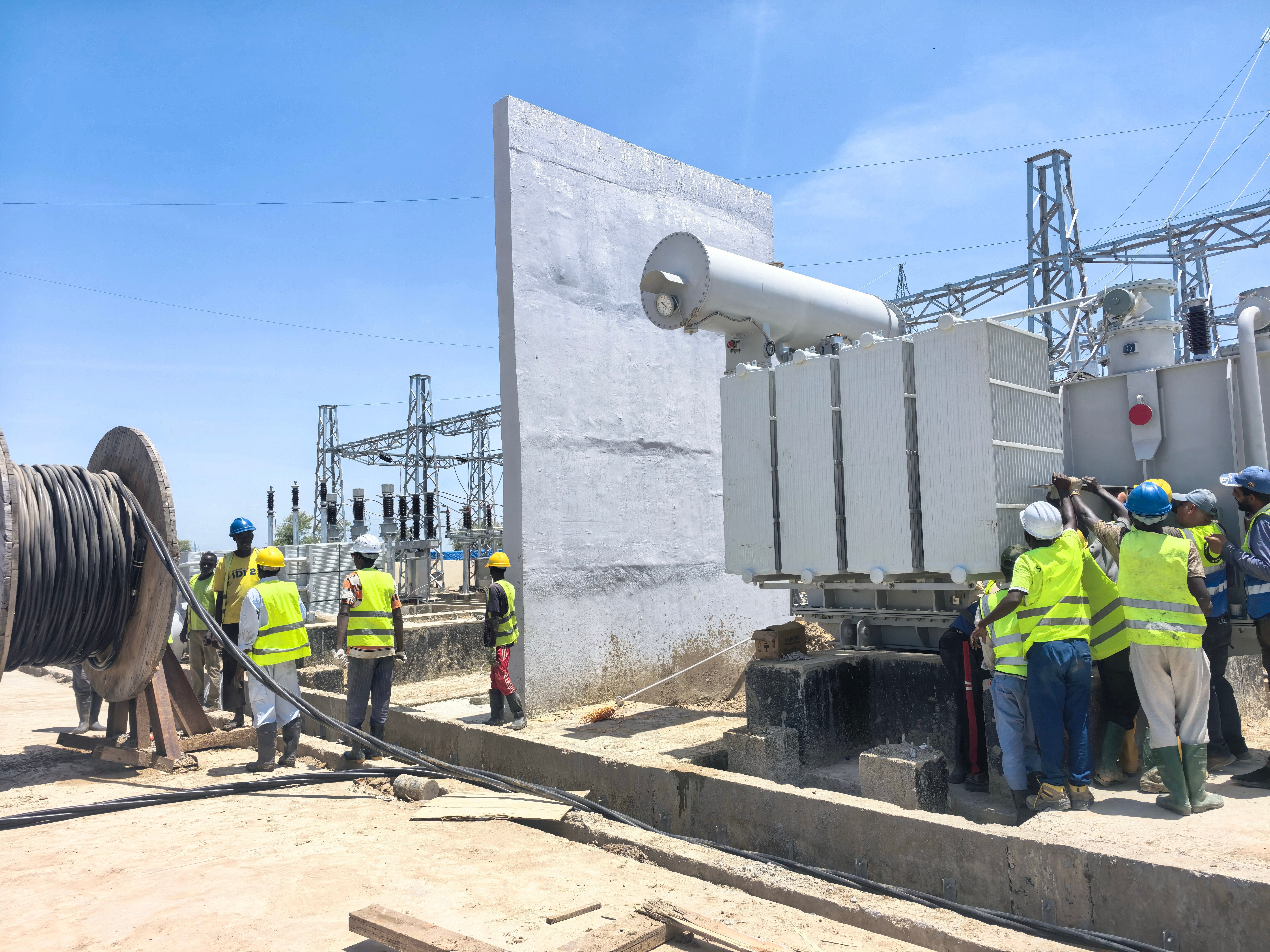
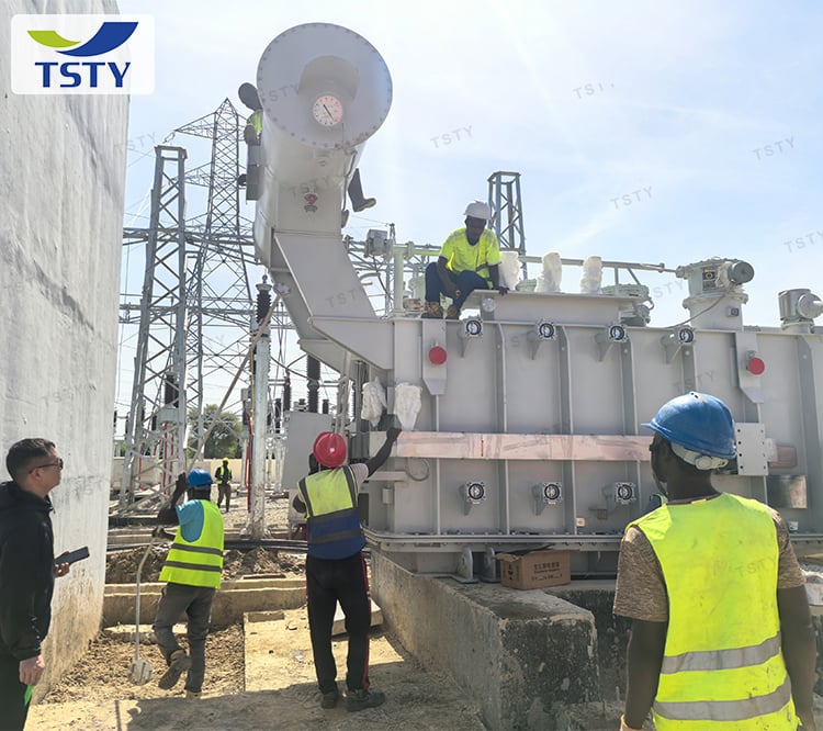



Reinforced winding clamping and low-impedance design enable the unit to endure severe fault currents without mechanical deformation, ensuring stability during grid contingencies.
Optimized core-winding geometry reduces overall dimensions by 15% compared to conventional 66kV designs, simplifying transport logistics and saving valuable substation space.
Factory-tuned impedance and tap ranges align with local utility requirements for voltage regulation, harmonic tolerance, and reactive power support in modernized networks.
Mature oil-paper insulation system with enhanced moisture barriers extends service life beyond 30 years, minimizing unplanned outages in mission-critical facilities.
No-load and load losses optimized for sub-transmission duty cycles reduce annual operating costs while maintaining acoustic levels below national limits for noise-sensitive sites.
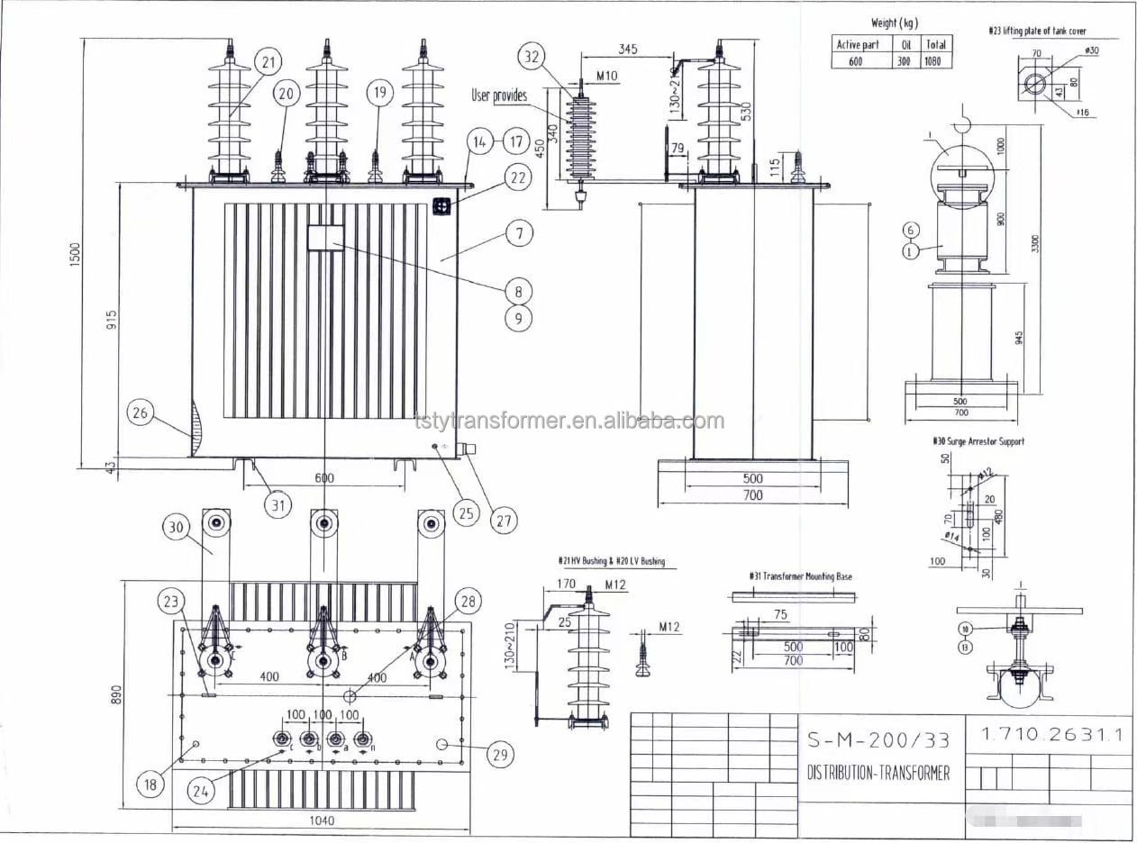
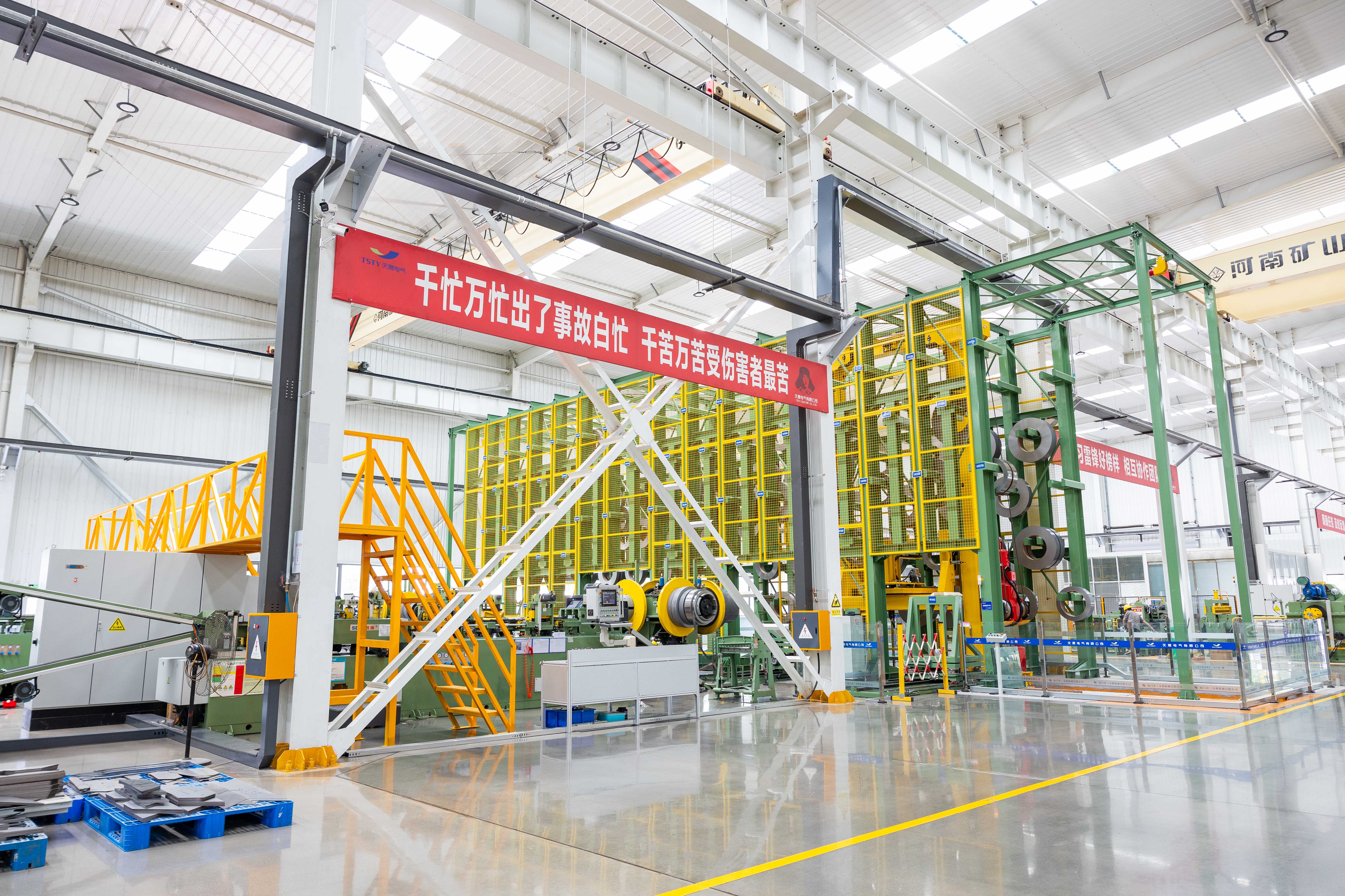
Engineers perform electromagnetic field simulation and short-circuit force calculation specific to 66kV class equipment, verifying structural integrity before production rather than relying on scaled-up distribution designs.
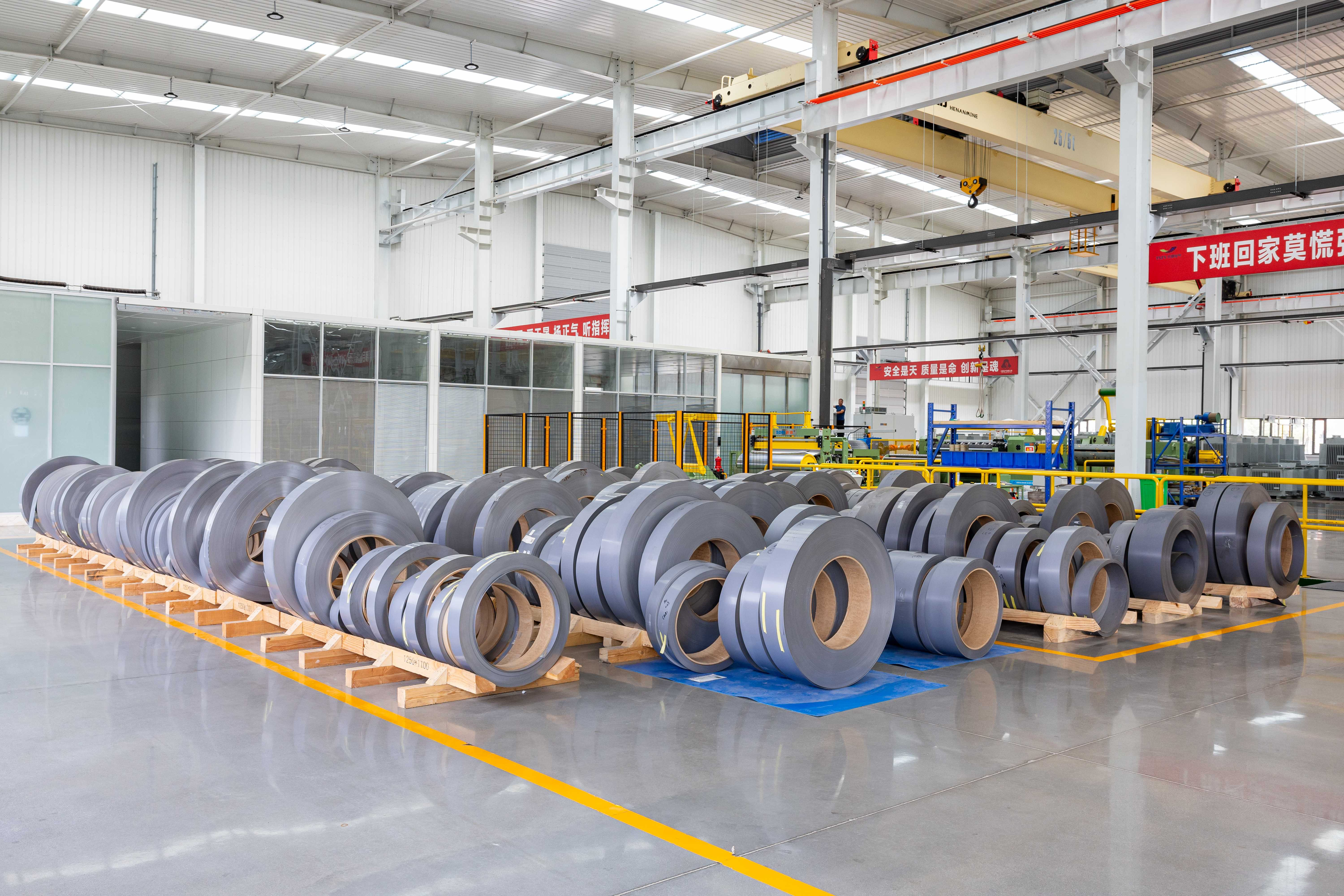
Bushings, tap changers, and insulating oils undergo type testing per IEC 60137/60214/60296 standards; supplier audits confirm batch consistency for components rated above 35kV.
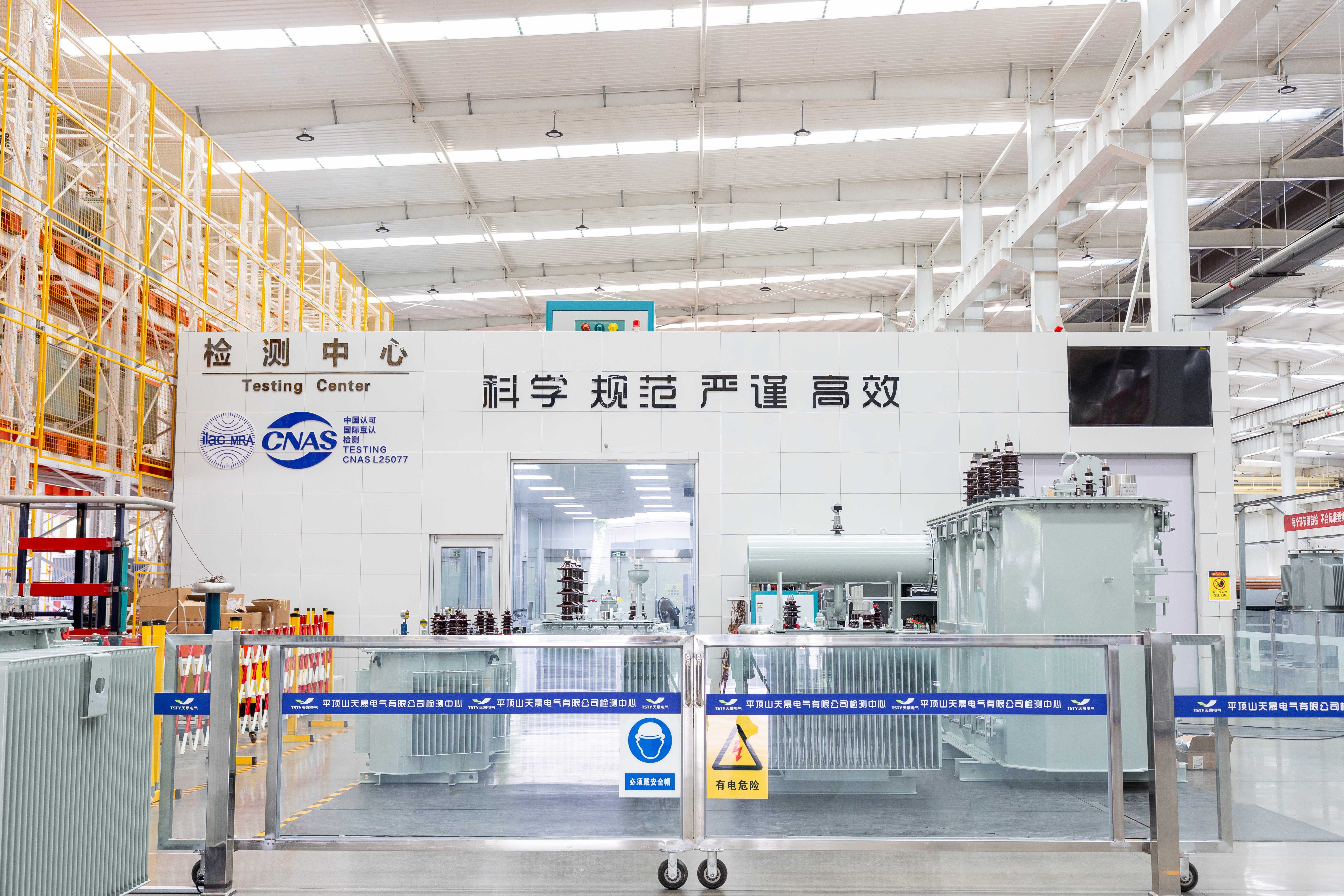
Each unit completes induced voltage withstand test with partial discharge measurement at 1.5× rated voltage, confirming insulation coordination for sub-transmission overvoltage profiles.
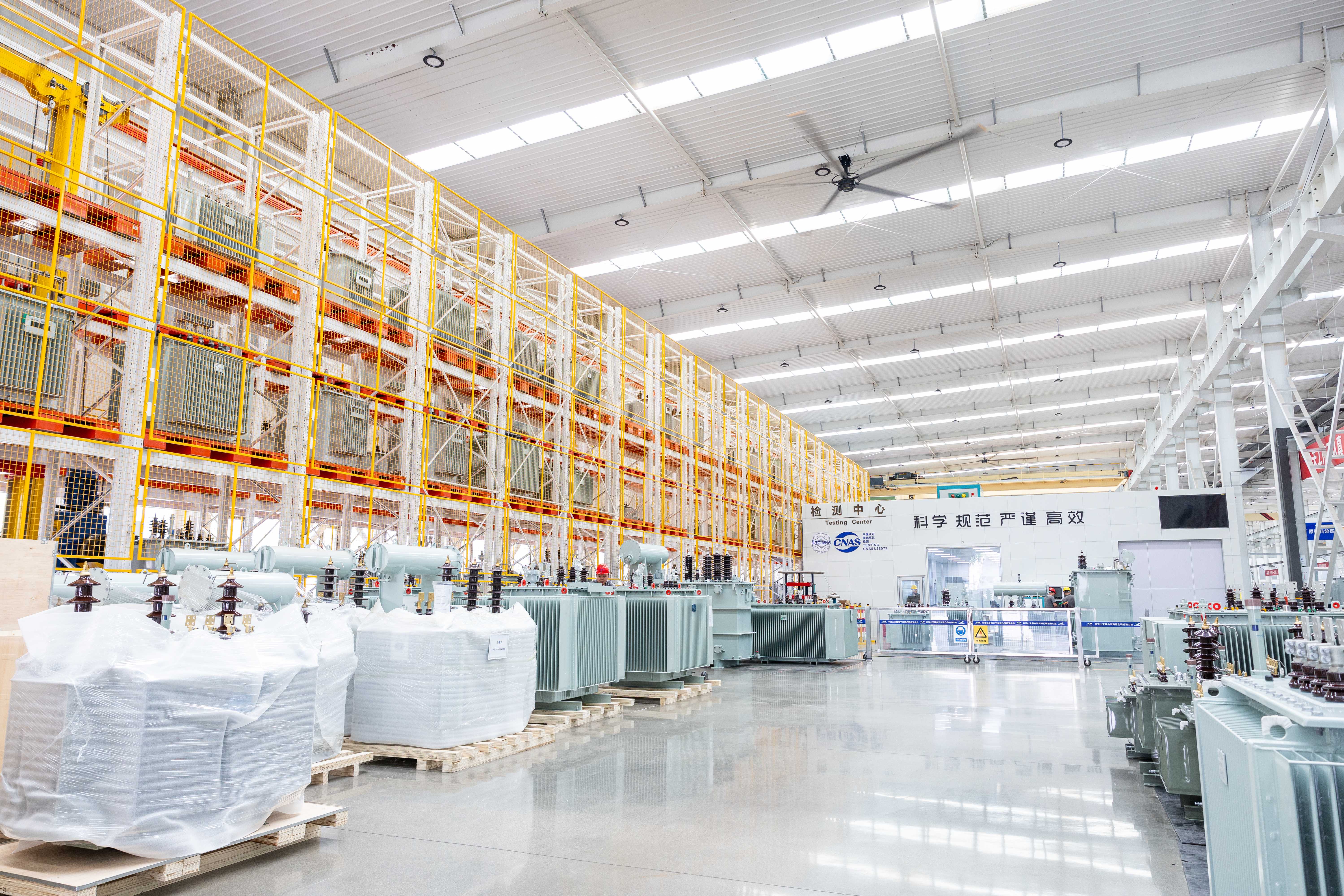
Units are validated against project-specific altitude, ambient temperature, and seismic zone data to guarantee rated capacity under actual installation conditions, not just standard reference values.
|
Rated capacity |
high Voltage |
Tap range |
low voltage |
Connection Group |
No-load loss |
Load loss |
No-load current |
Impedance voltage(%) |
|
2000 |
60 |
±8×1.25% |
6.3 |
YNd11 |
1.8 |
14.7 |
0.3 |
8.0 |
|
2500 |
2.1 |
17.4 |
0.3 |
|||||
|
3150 |
2.4 |
20.7 |
0.3 |
|||||
|
4000 |
3.1 |
24.6 |
0.3 |
|||||
|
5000 |
3.7 |
27.6 |
0.3 |
|||||
|
6300 |
4.4 |
30.8 |
0.3 |
9.0 |
||||
|
8000 |
5.3 |
36.5 |
0.3 |
|||||
|
10000 |
6.2 |
43.0 |
0.3 |
|||||
|
12500 |
7.4 |
51.1 |
0.3 |
|||||
|
16000 |
8.9 |
62.8 |
0.3 |
|||||
|
20000 |
10.6 |
76.1 |
0.3 |
|||||
|
25000 |
12.5 |
90.0 |
0.3 |
|||||
|
31500 |
14.8 |
108.0 |
0.3 |
|||||
|
40000 |
17.7 |
126.9 |
0.3 |
|||||
|
50000 |
20.9 |
150.3 |
0.3 |
|||||
|
63000 |
24.7 |
178.2 |
0.3 |
|||||
|
75000 |
28.2 |
203.1 |
0.3 |
|||||
|
90000 |
32.3 |
232.9 |
0.3 |
|||||
|
100000 |
34.9 |
252.0 |
0.3 |
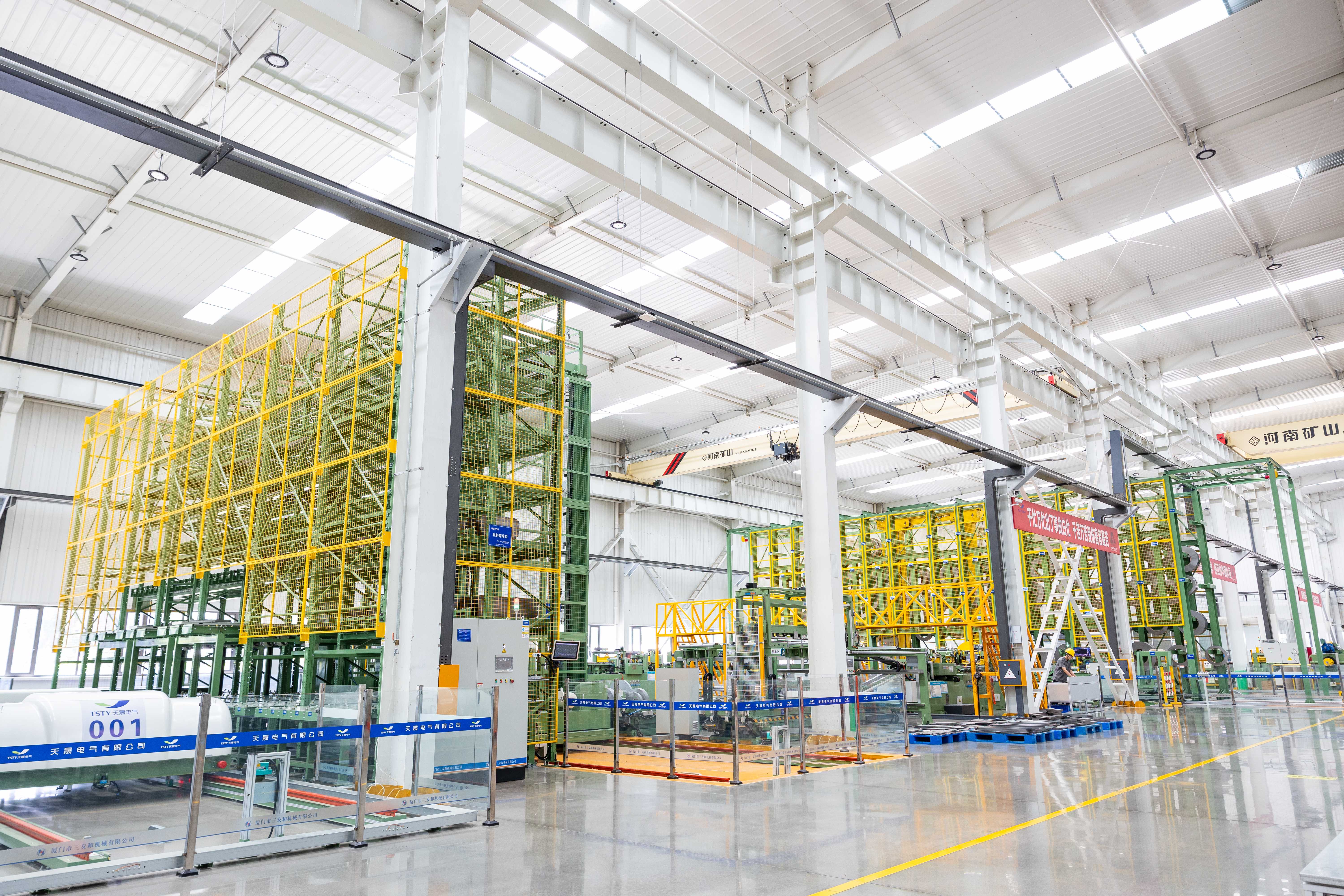
Galvanized steel for standard outdoor use or stainless steel for coastal/chemical environments; custom RAL color matching available to align with site branding or environmental blending requirements.
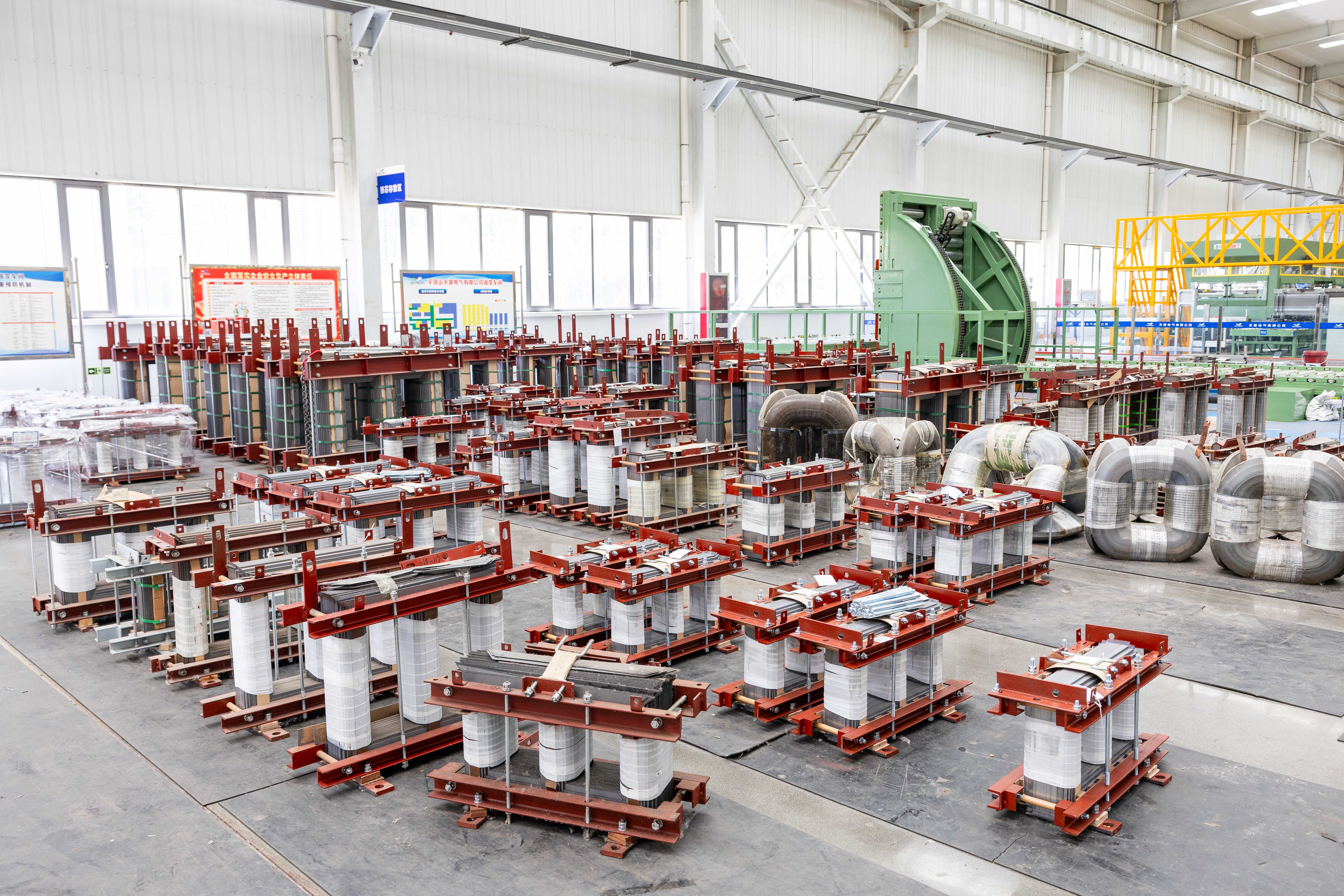
Sealed-tank configuration for maintenance-free operation in stable climates, or conservator with nitrogen blanket for high-altitude sites requiring pressure management and moisture exclusion.
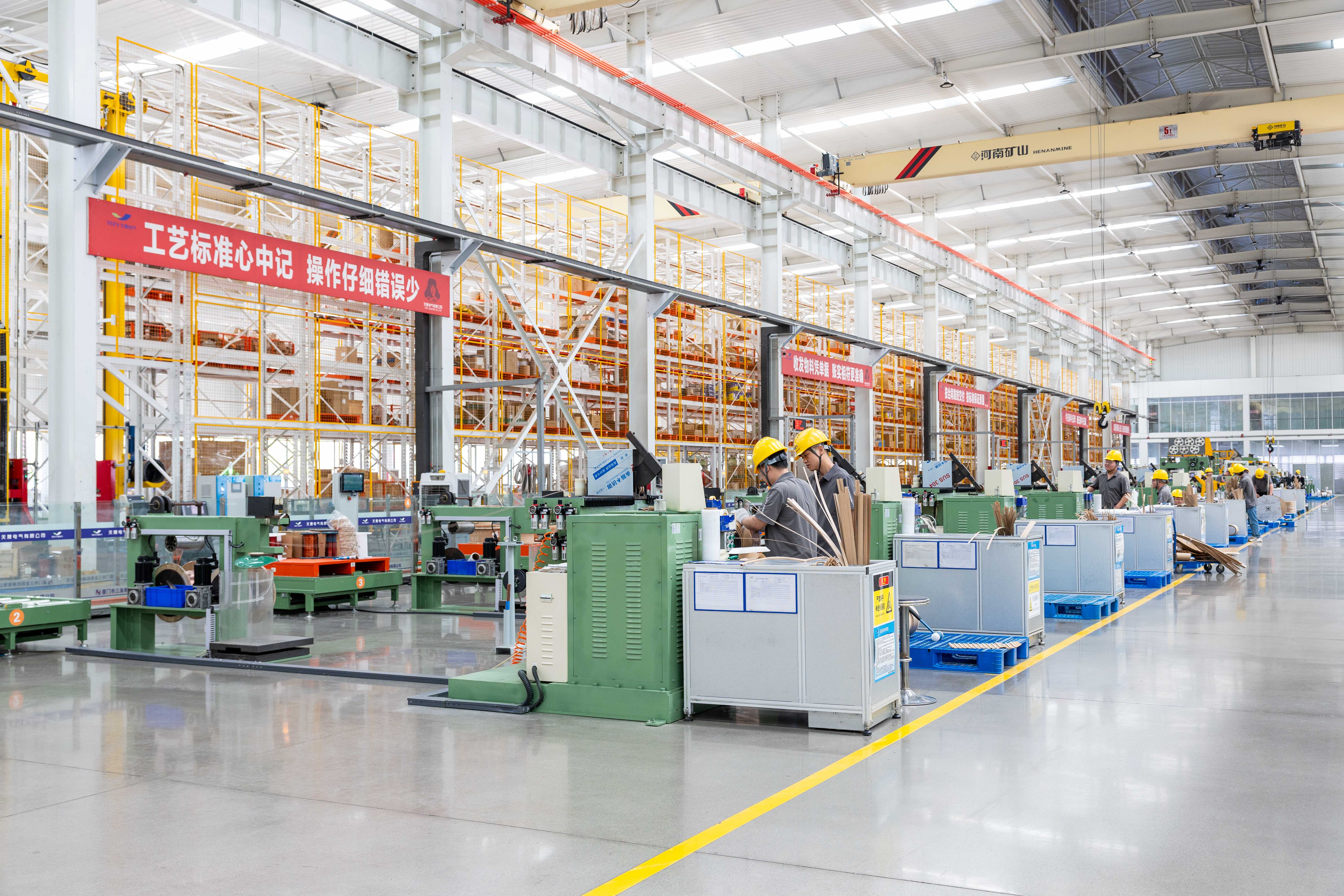
Off-circuit tap changer for fixed-ratio applications, or on-load tap changer (OLTC) with customized step voltages and position counts to support dynamic grid voltage control; tap ranges adjustable to match utility tolerance bands.
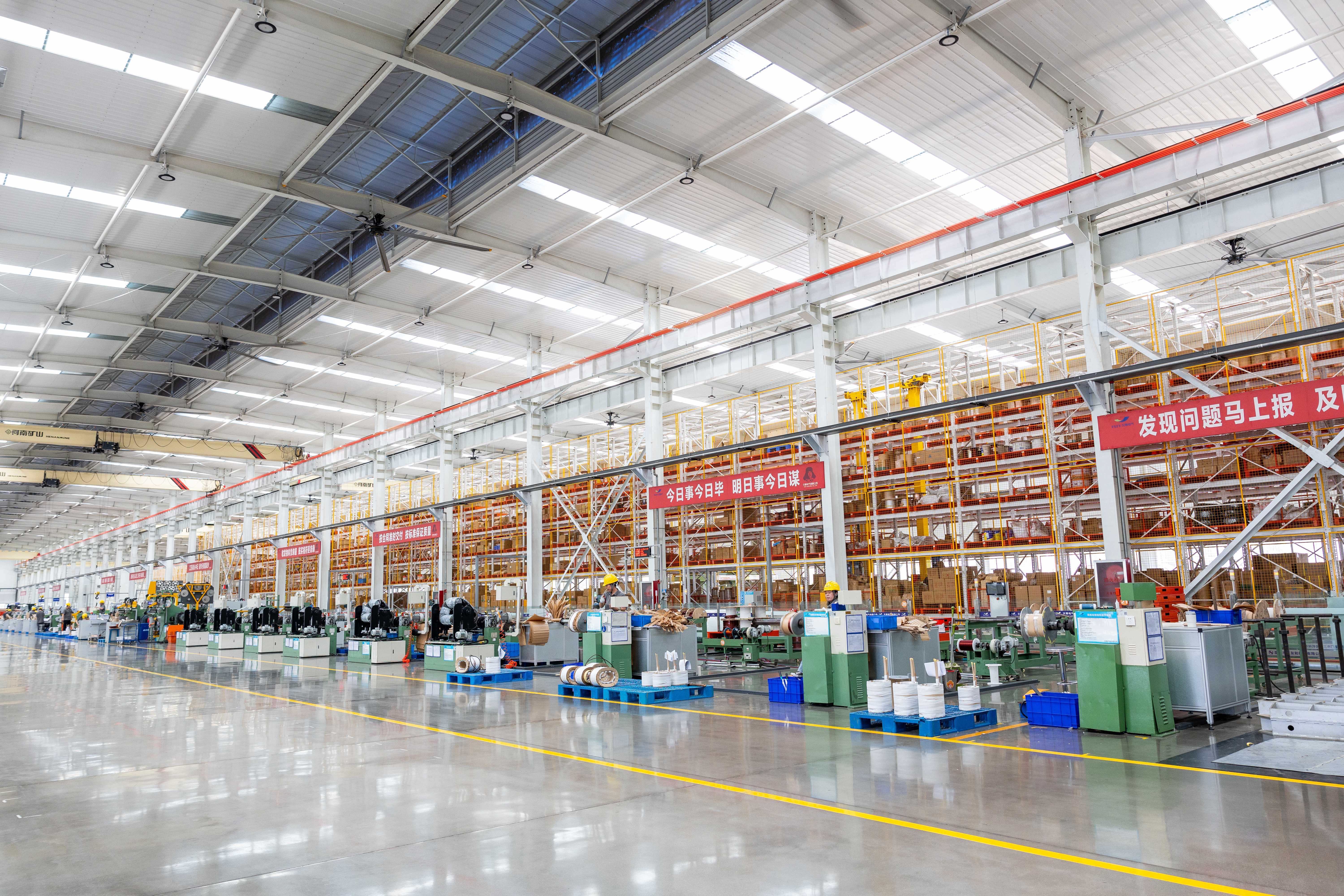
Low-profile tank design with reinforced lifting points for restricted-height transport routes; optional heavy-duty casters and jacking pads for indoor positioning where overhead cranes are unavailable.
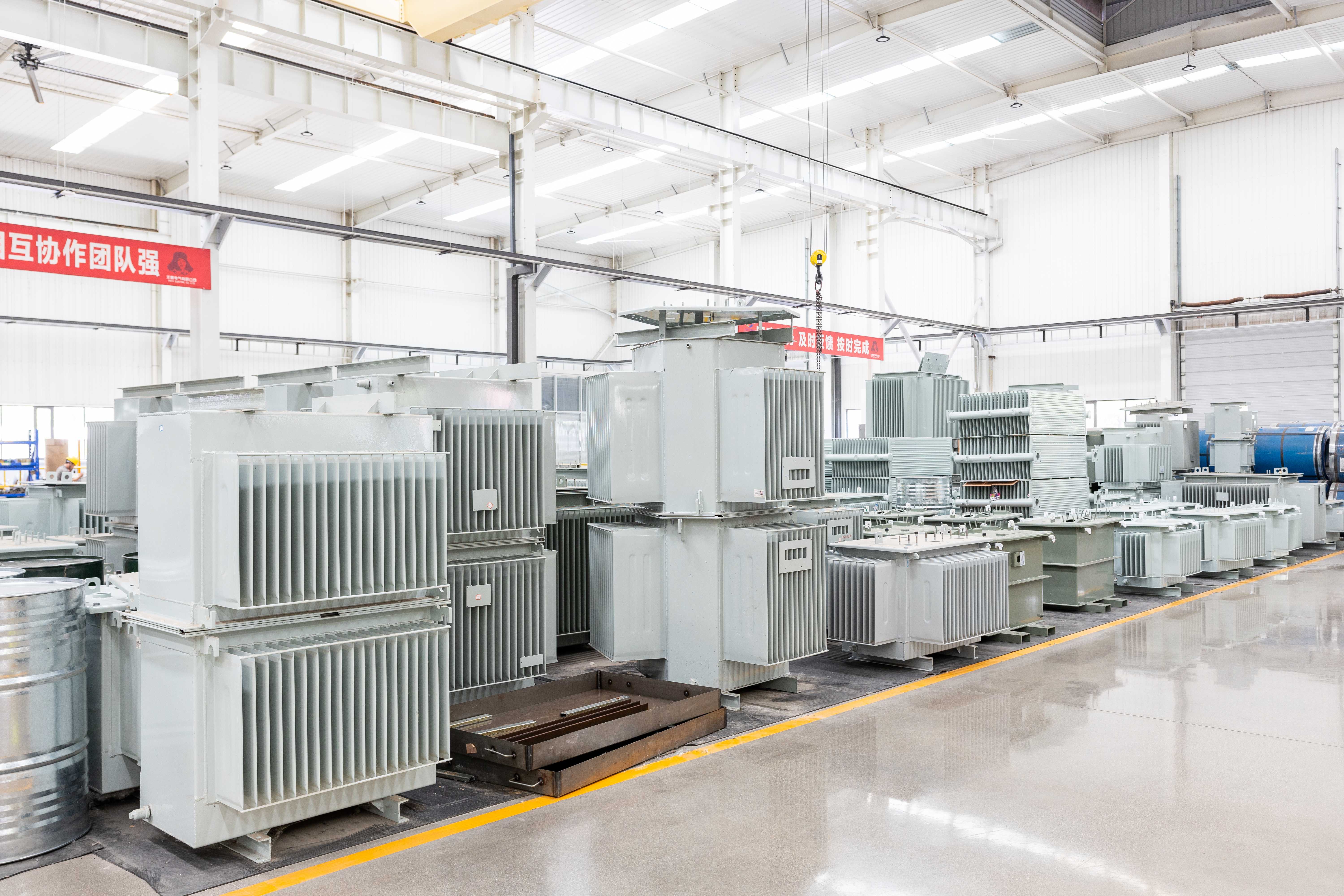
WTI/OTI sensors with analog/digital outputs and alarm/trip contacts for SCADA integration; optional dissolved gas analysis (DGA) monitors for early fault detection in critical sub-transmission assets.
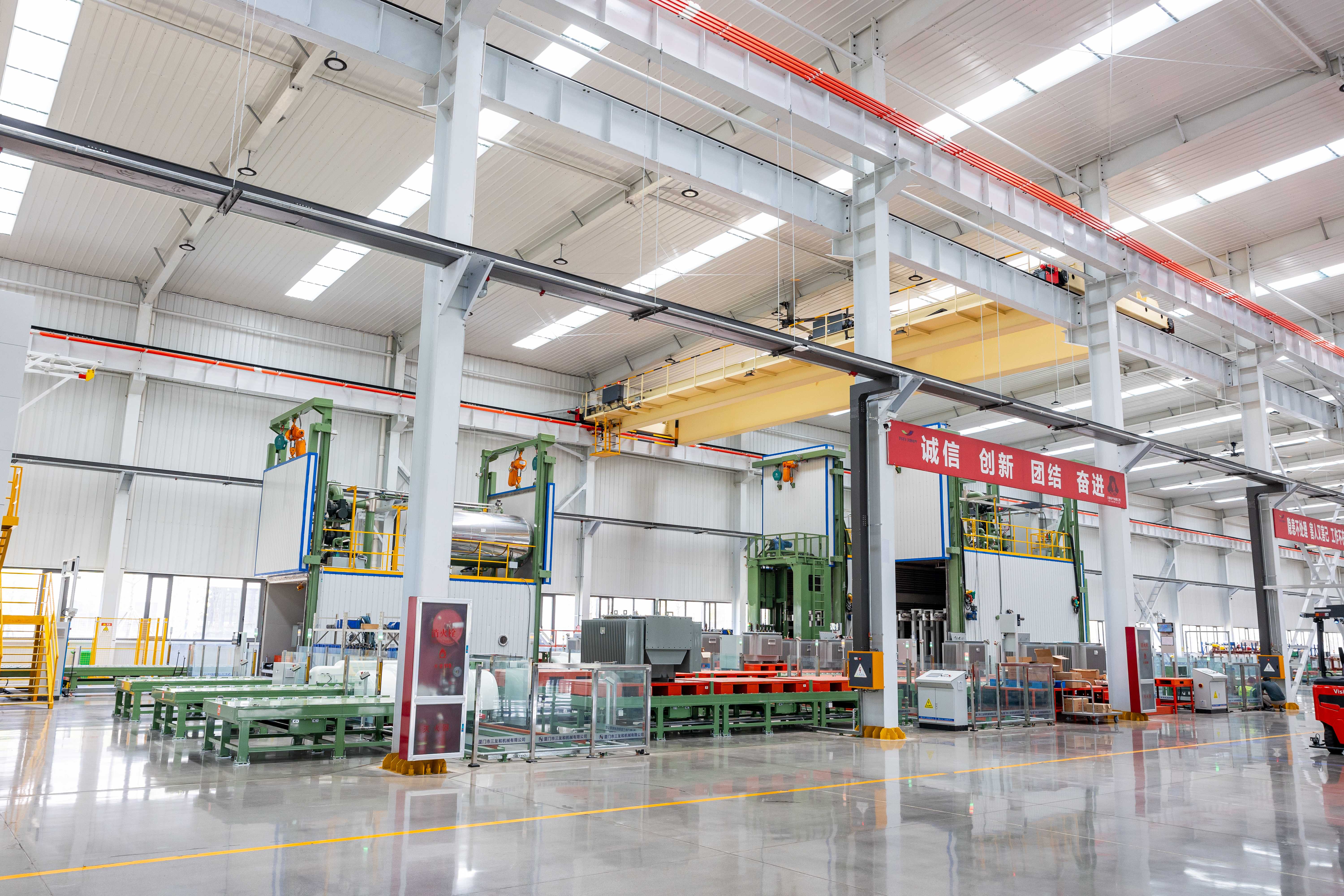
No-load and load losses tailored to project-specific tariff structures or regulatory efficiency tiers (e.g., S20/S22), balancing capital expenditure against lifecycle operating costs.
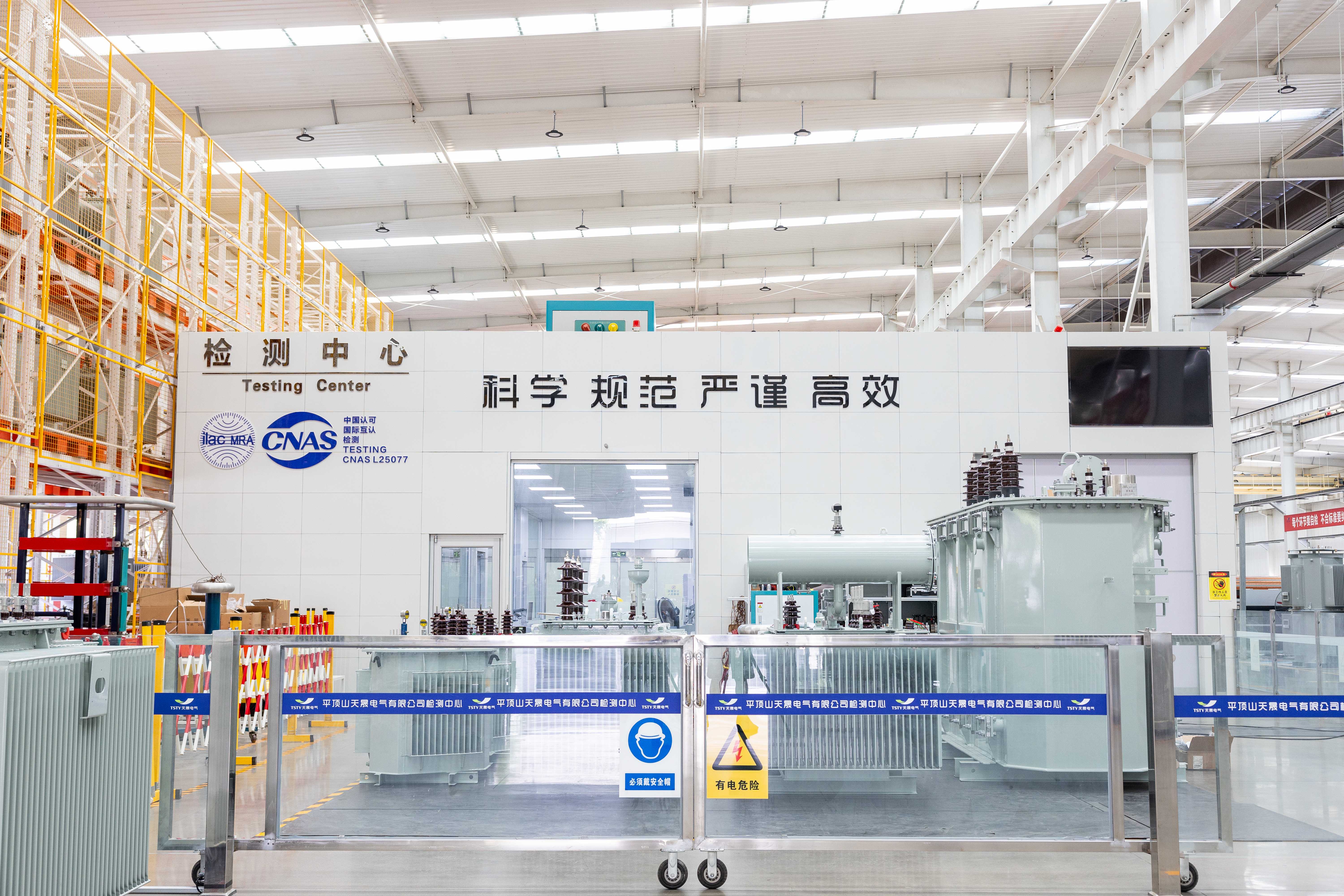
Adjustable bushing clearances, mounting hole patterns, and cable entry positions to fit existing foundation footprints; nameplates available in bilingual formats or with QR codes linking to digital documentation.


Tell us your project requirements—voltage level, environment, grid code, or delivery timeline—and we’ll provide a compliant, optimized solution.





 EN