
Verified short-circuit withstand and low noise for national grid and heavy industry.
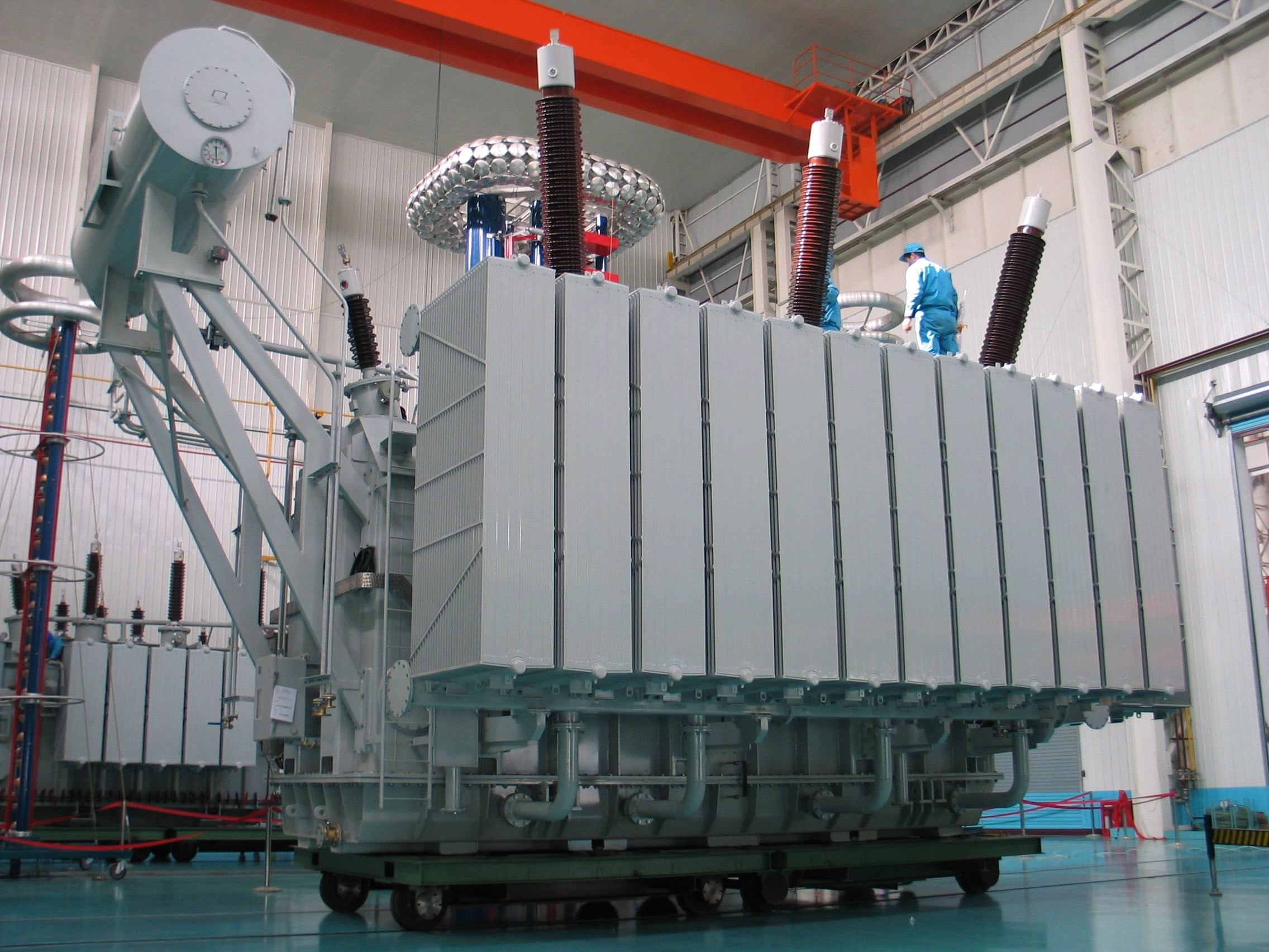
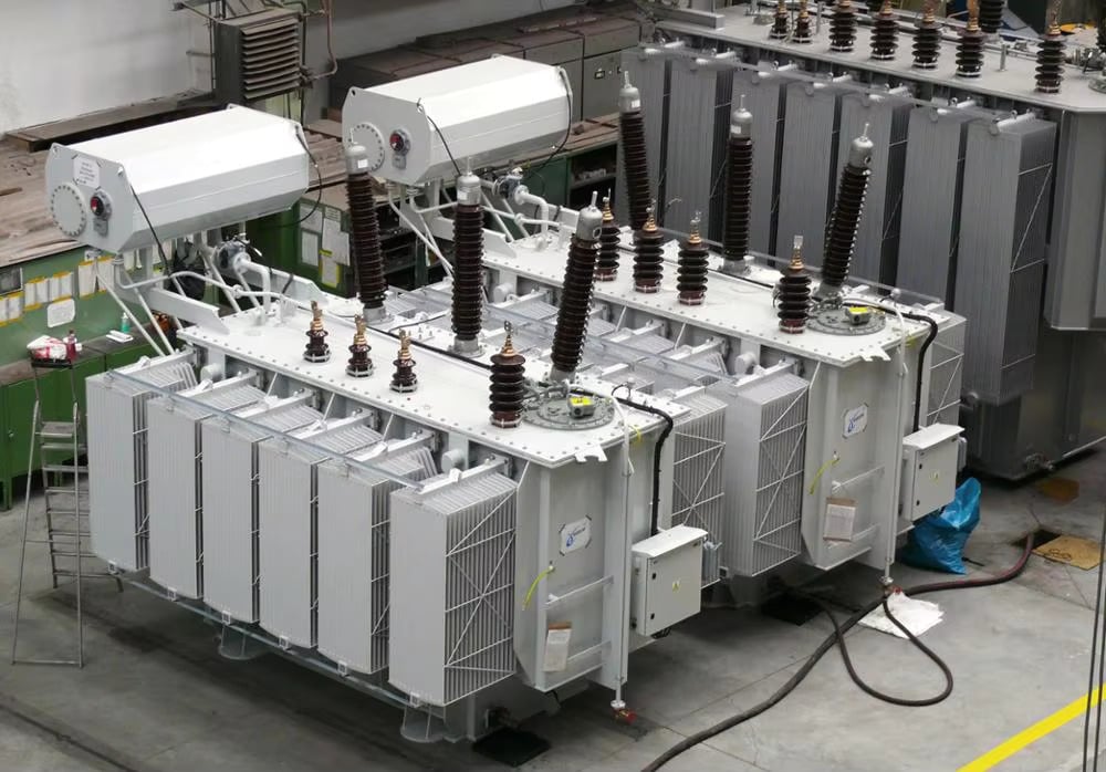
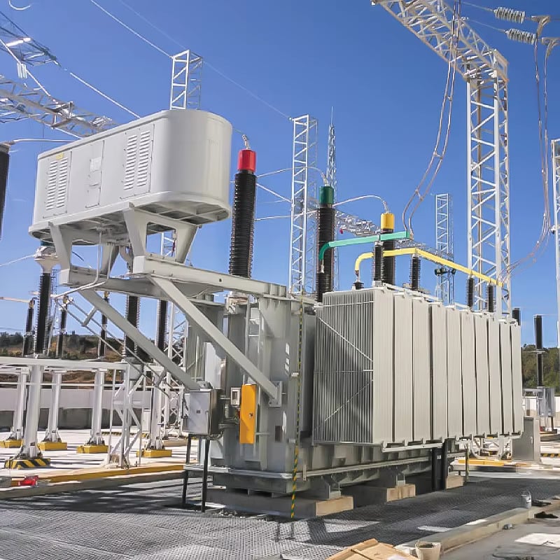
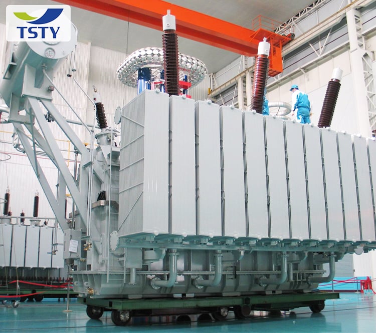




Specialized electromagnetic design reduces no-load losses by 20% and load losses by 5% versus national standards, delivering measurable annual cost reductions over decades of service.
Multi-point acoustic engineering targets electromagnetic and mechanical noise at origin, achieving 3–5 dB(A) below national limits without relying solely on external barriers or enclosures.
Passed the National Transformer Quality Inspection and Testing Center’s sudden short-circuit test on first attempt, confirming winding clamping and core support can withstand electromagnetic forces during grid faults.
Die-cast sealing components validated via fluorescence, positive-pressure, and negative-pressure testing minimize oil seepage risks across all thermal cycles and operating pressures.
Factory-configurable on-load or off-excitation tap changers adapt to dynamic grid voltage control needs or fixed-ratio applications, optimizing lifecycle performance for specific project requirements.
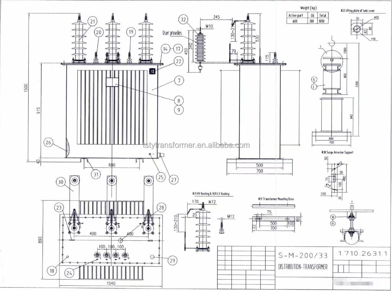
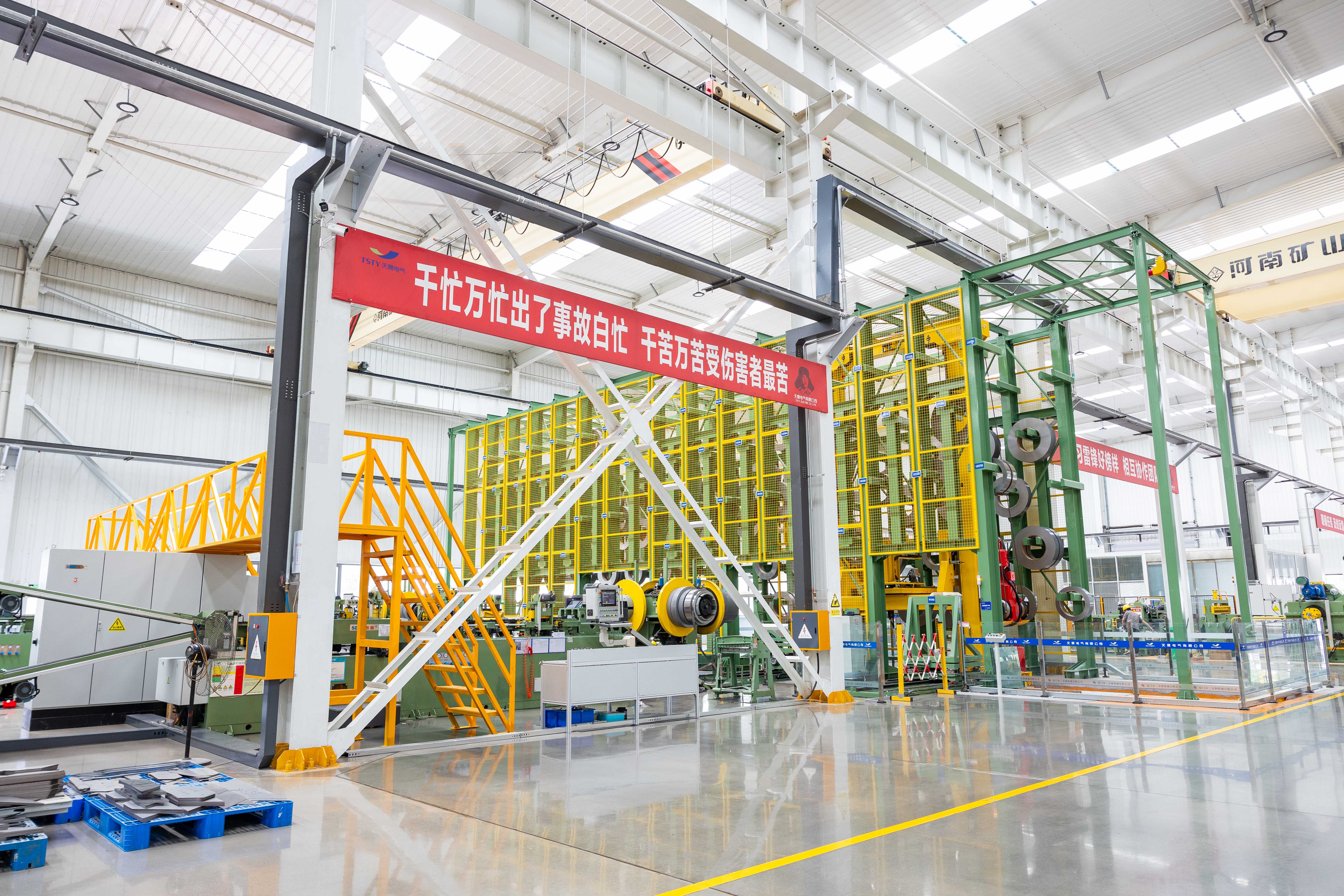
No-load and load losses are measured against project-specific efficiency targets rather than generic standards, with test data traceable to National Transformer Quality Inspection and Testing Center protocols to verify claimed savings.
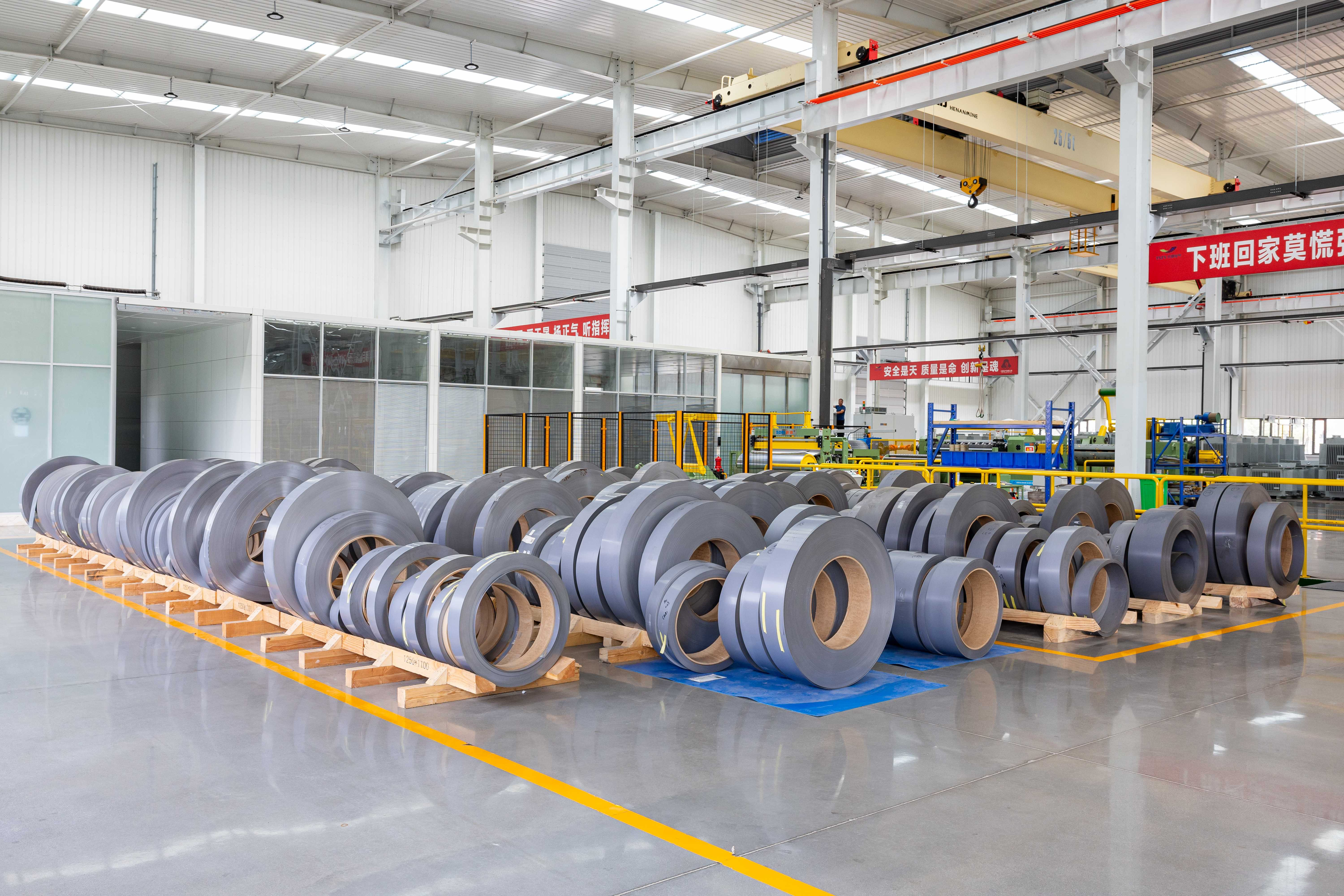
Noise reduction measures are validated through component-level sound intensity measurements during assembly, ensuring suppression targets are met at source rather than relying on post-production corrections.
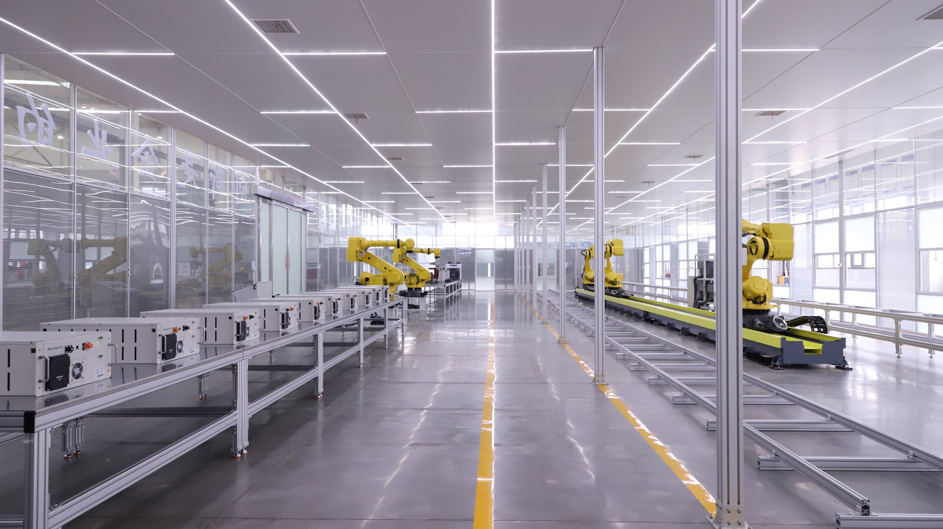
Electromagnetic finite-element analysis validates winding clamping pressure and core support structure before production, ensuring mechanical integrity aligns with verified test performance rather than empirical design rules.
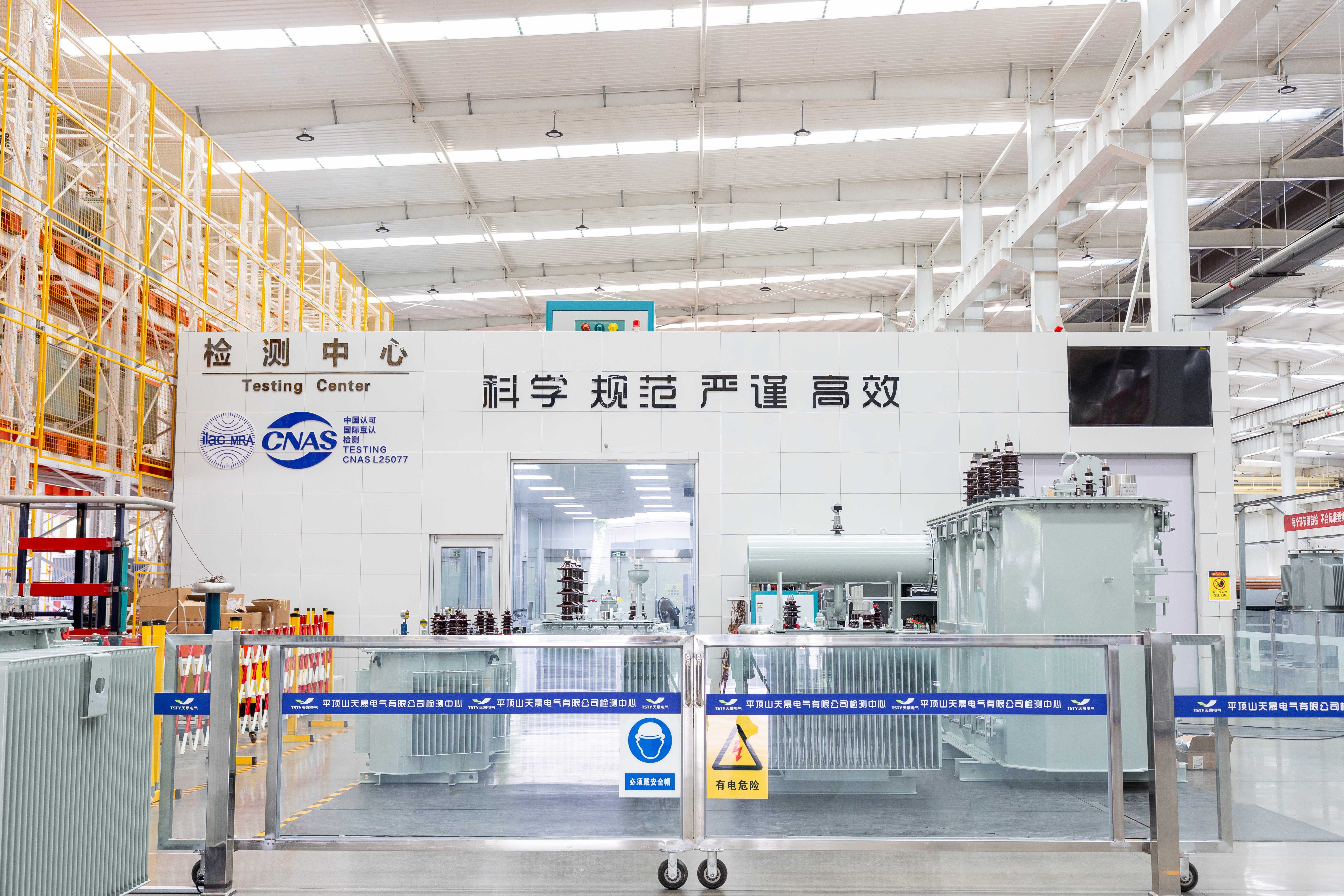
Each unit completes lightning impulse, switching impulse, and induced voltage withstand tests per IEC 60076 and GB/T 1094, with partial discharge measurements confirming insulation coordination for 220kV system overvoltage profiles.
|
Rated Capacity (KVA) |
Voltage Combination and Tapping Range |
Vector Group |
No Load Loss (KW) |
Load Loss (KW) |
No Load Current (%) |
Capacity Allocation (%) |
Impedance (%) |
||
|
HV (KV) |
MV (KV) |
LV(KV) |
|||||||
|
31500 |
220±8x1.25% 230±8x1.25% |
69 115 121 |
6.3 |
YNyn0d11 |
28 |
145 |
0.77 |
100/100/100 |
HV-MV |
|
40000 |
33 |
174 |
0.73 |
||||||
|
50000 |
38 |
205 |
0.74 |
||||||
|
63000 |
45 |
244 |
0.69 |
||||||
|
90000 |
10.5 |
58 |
315 |
0.54 |
|||||
|
120000 |
74 |
390 |
0.54 |
||||||
|
150000 |
86 |
463 |
0.48 |
||||||
|
180000 |
99 |
568 |
0.48 |
||||||
|
240000 |
120 |
704 |
0.43 |
||||||
Carbon steel with hot-dip galvanizing for standard outdoor durability, or stainless steel for coastal/high-corrosion environments; custom RAL color matching available for site aesthetic integration.
Sealed-tank design for reduced maintenance in stable climates, or conservator with nitrogen blanket for high-altitude sites requiring pressure equalization and moisture exclusion.
On-load tap changer (OLTC) for dynamic grid voltage control, or off-excitation tap changer for fixed-ratio applications; tap ranges and step voltages adjustable to match utility tolerance bands.
Low-profile tank design with reinforced lifting points for restricted-height transport routes; optional heavy-duty casters and jacking pads for indoor positioning where overhead cranes are unavailable.
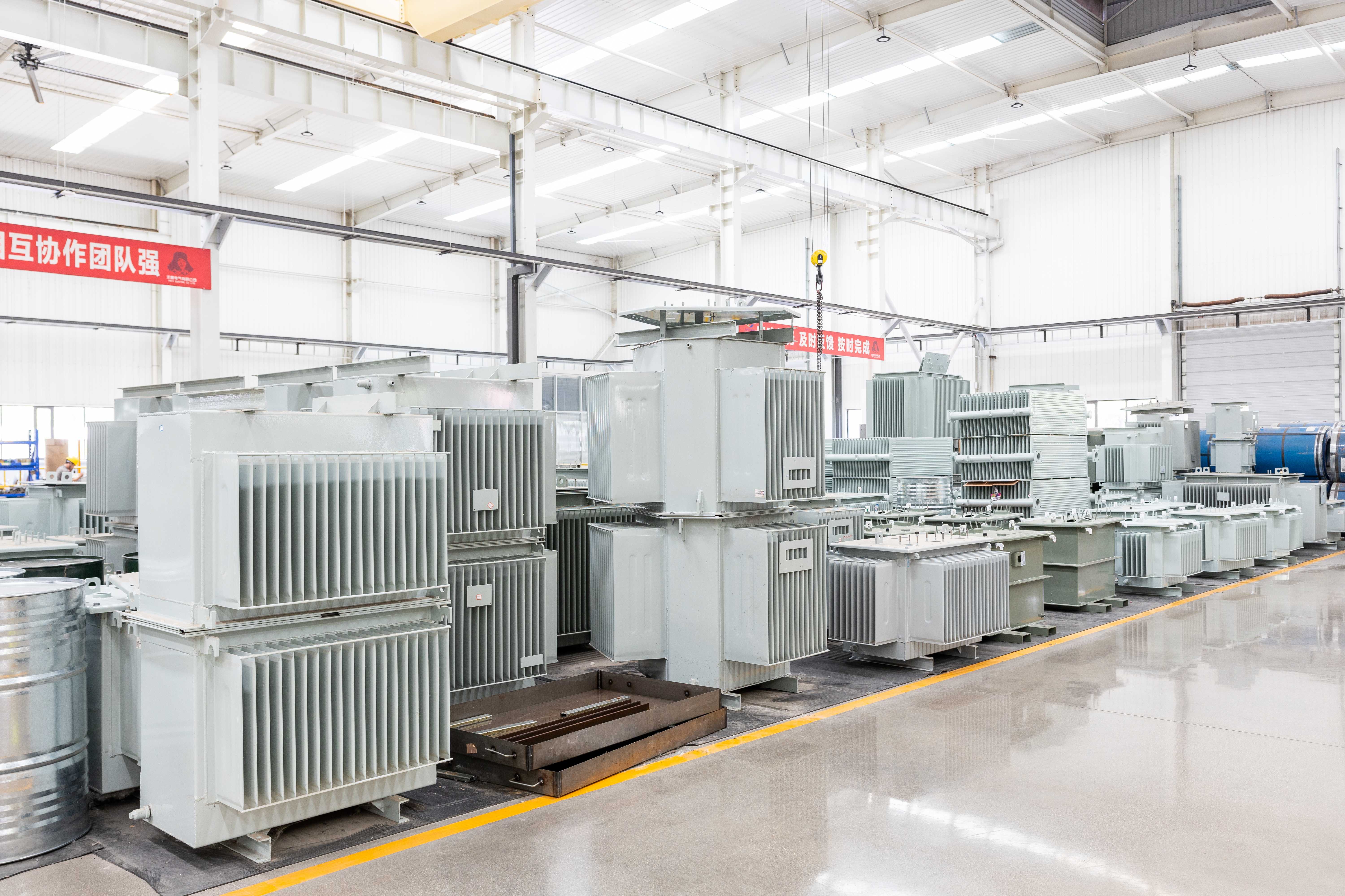
WTI/OTI sensors with analog/digital outputs and alarm/trip contacts for SCADA integration; optional dissolved gas analysis (DGA) monitors for early fault detection in critical ultra-high-voltage assets.
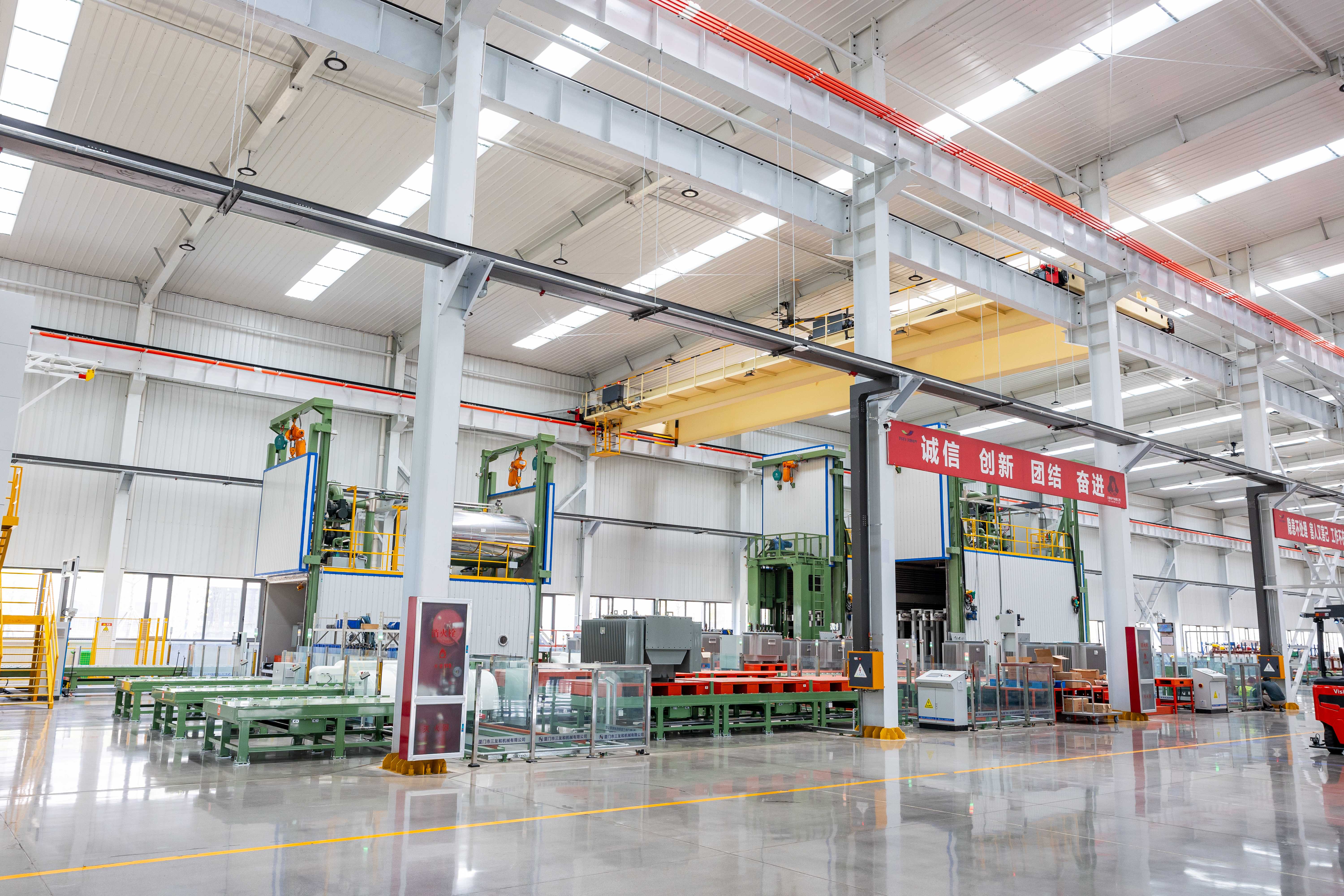
No-load and load losses tailored to project-specific tariff structures or regulatory efficiency tiers, balancing capital expenditure against lifecycle operating costs while maintaining low temperature rise.
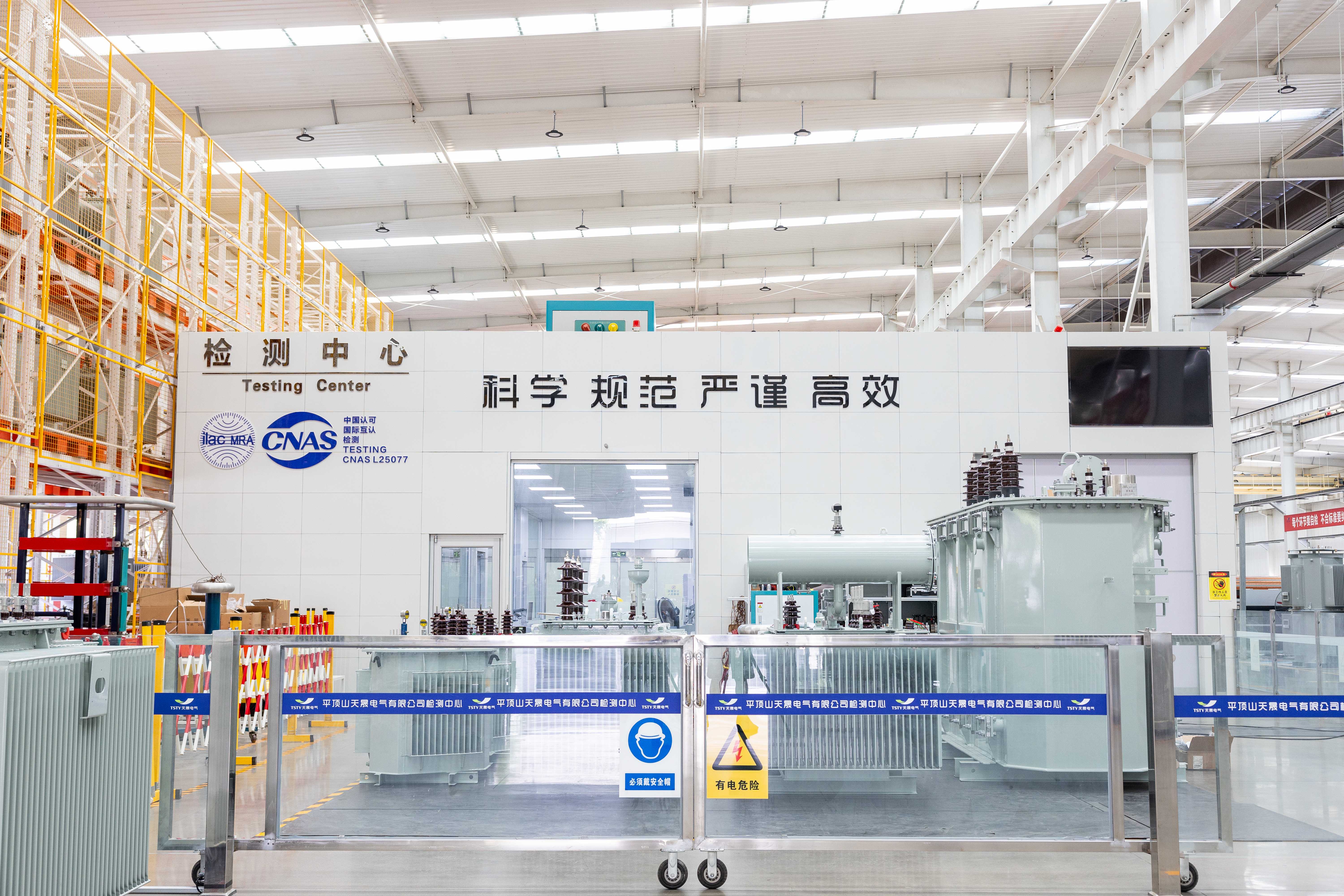
Adjustable bushing clearances, mounting hole patterns, and cable entry positions to fit existing foundation footprints; nameplates available in bilingual formats or with QR codes linking to digital documentation.


Tell us your project requirements—voltage level, environment, grid code, or delivery timeline—and we’ll provide a compliant, optimized solution.





 EN