
Medium-high voltage, IEC/GOST certified oil-immersed transformer for 33/35kV regional grid interconnection and industrial power supply
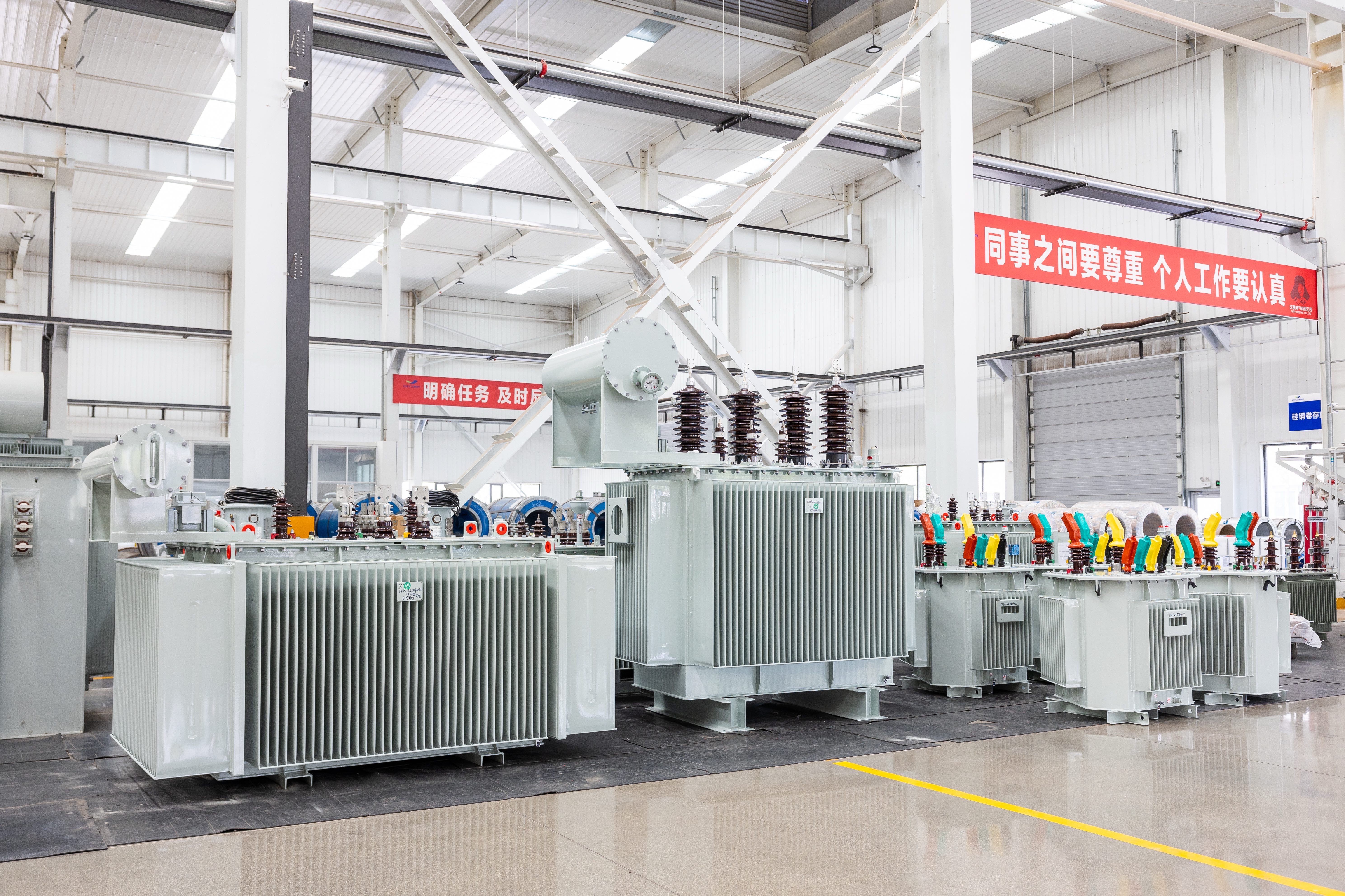
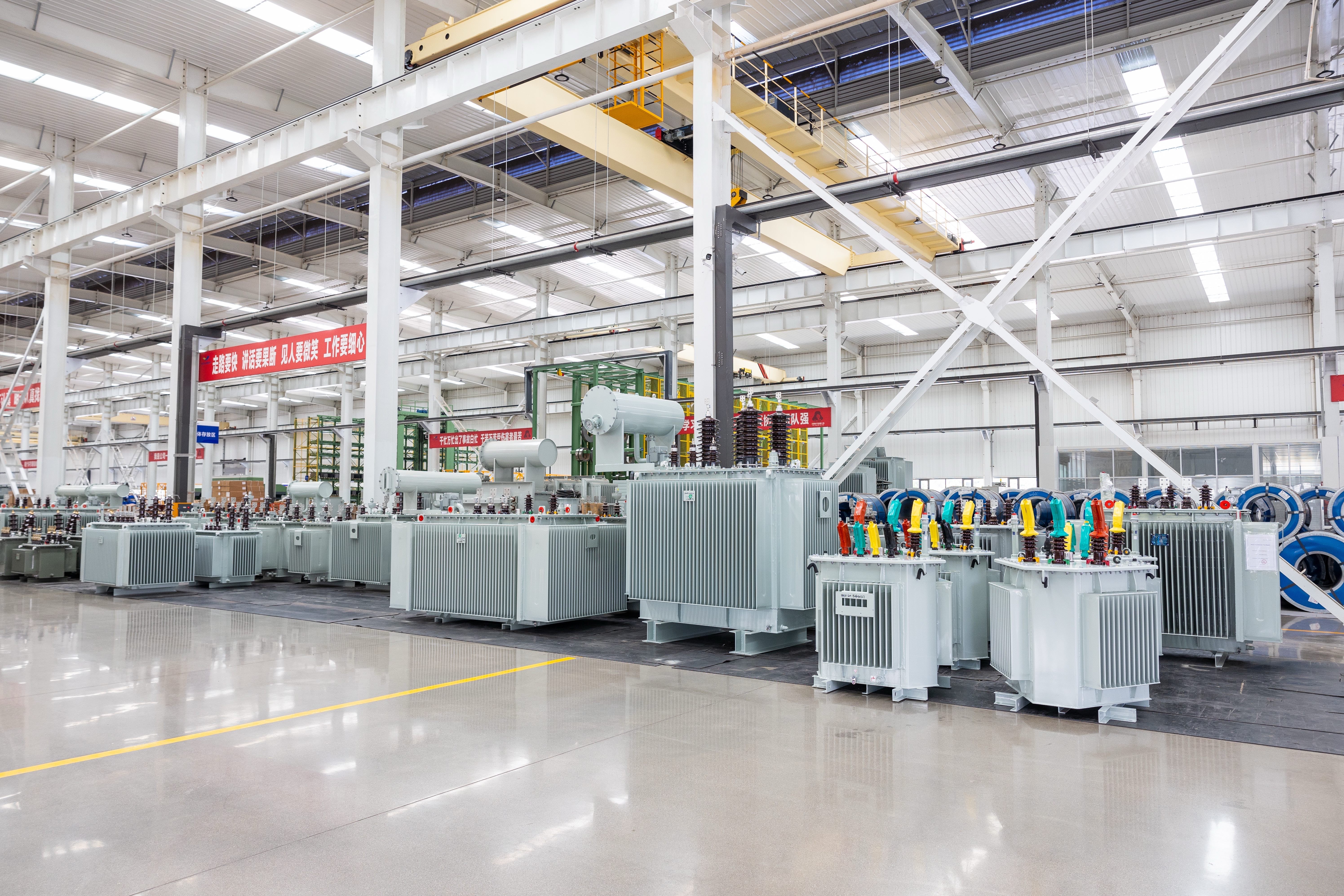
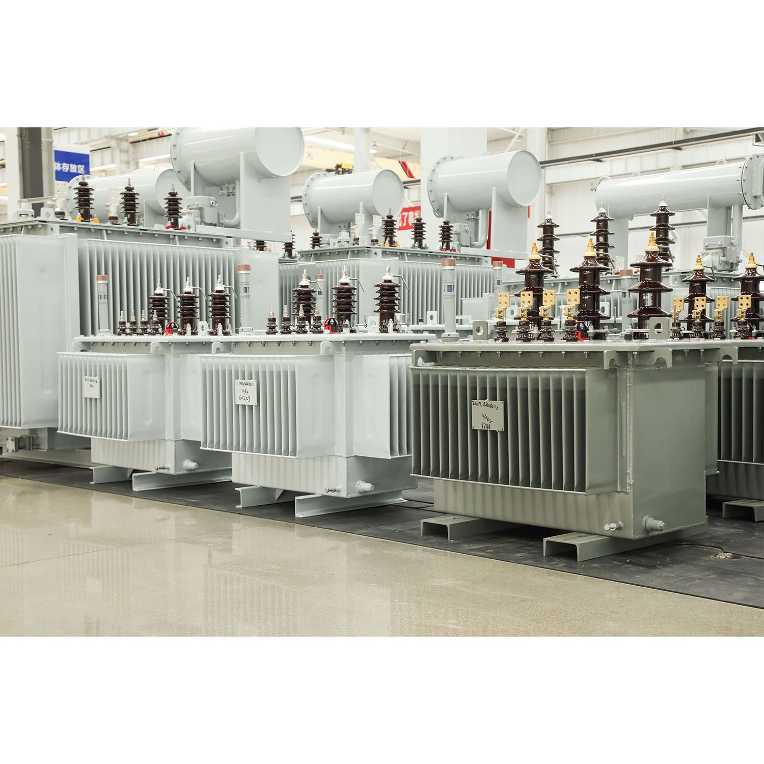
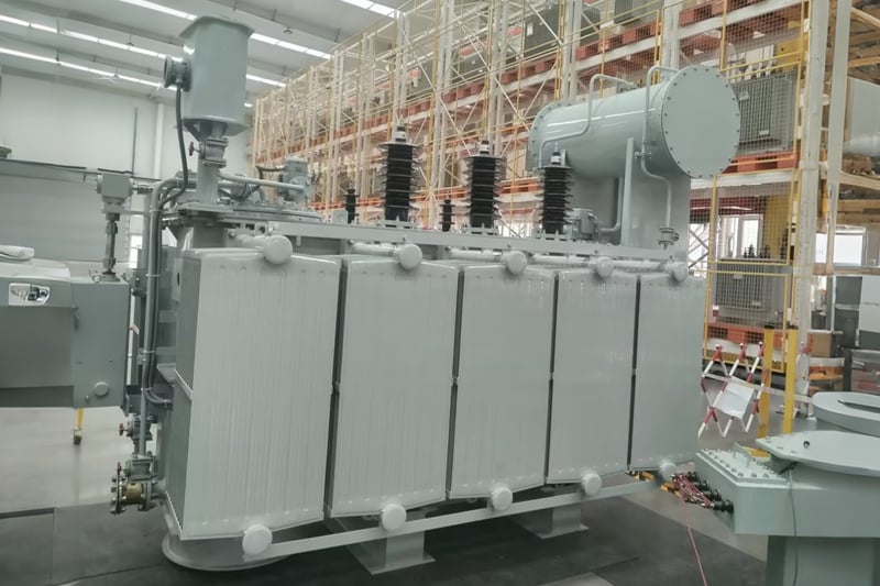
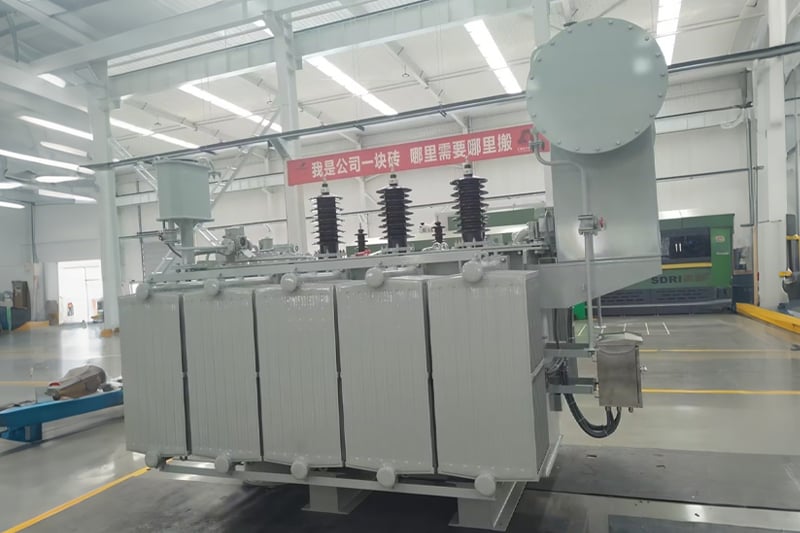



Enhanced oil-paper insulation system with optimized winding spacing withstands 35kV switching surges and lightning impulses, ensuring stable operation in electrically noisy industrial environments.
Optimized core-winding geometry and cooling duct design accommodate sustained 120% overload during peak demand or contingency scenarios without accelerated aging.
Factory-configurable secondary outputs (10kV or 0.4kV) eliminate the need for additional step-down transformers, reducing footprint and total cost of ownership in multi-tier distribution networks.
Reinforced tank walls and clamping structures resist transportation stress and seismic forces, meeting site-specific installation requirements for remote or seismically active zones.
Noise levels consistently below national limits through precision core stacking and vibration-damping mounts, enabling deployment near residential boundaries or noise-sensitive facilities.
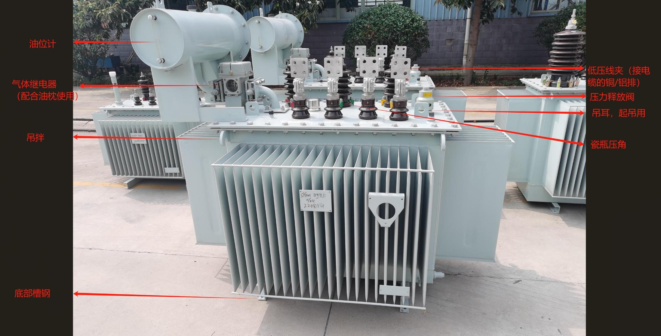
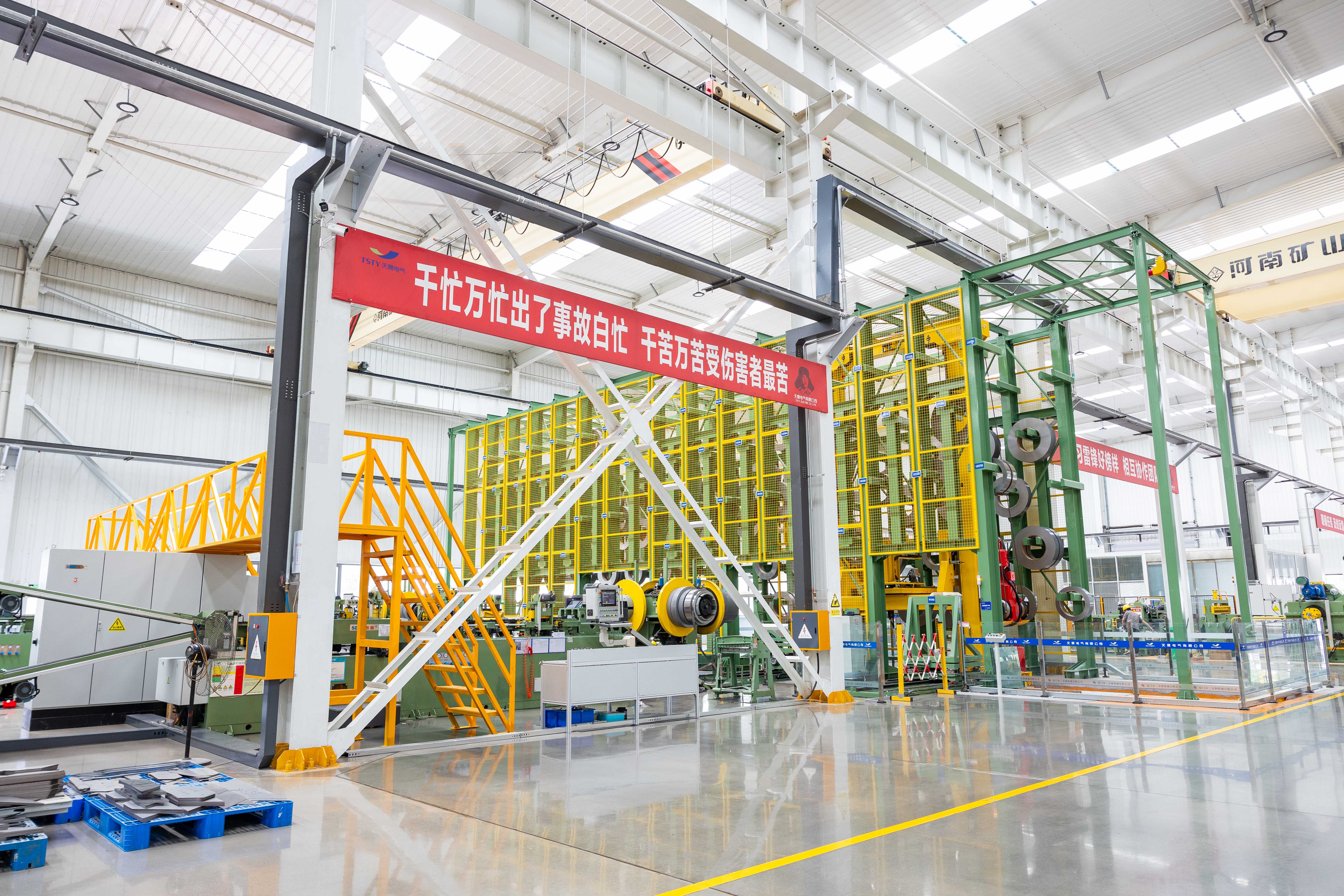
Dedicated engineers review client-provided single-line diagrams, ambient data, and grid codes to verify design compatibility before production, preventing field rework due to mismatched specifications.
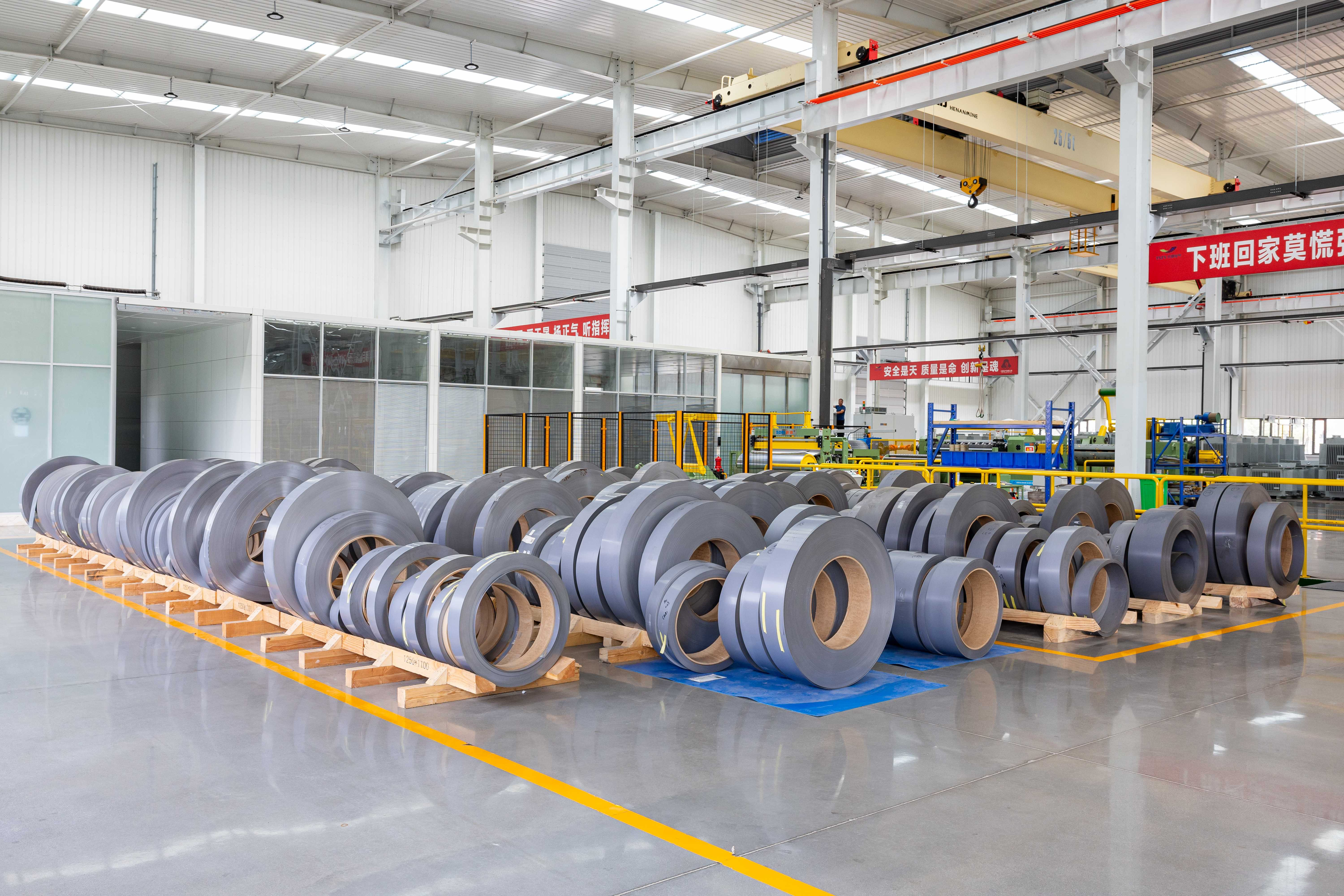
All core steel, copper conductors, and insulating oils are sourced from ISO-certified suppliers with batch-level documentation; incoming materials undergo pre-production testing to ensure consistency across every unit.
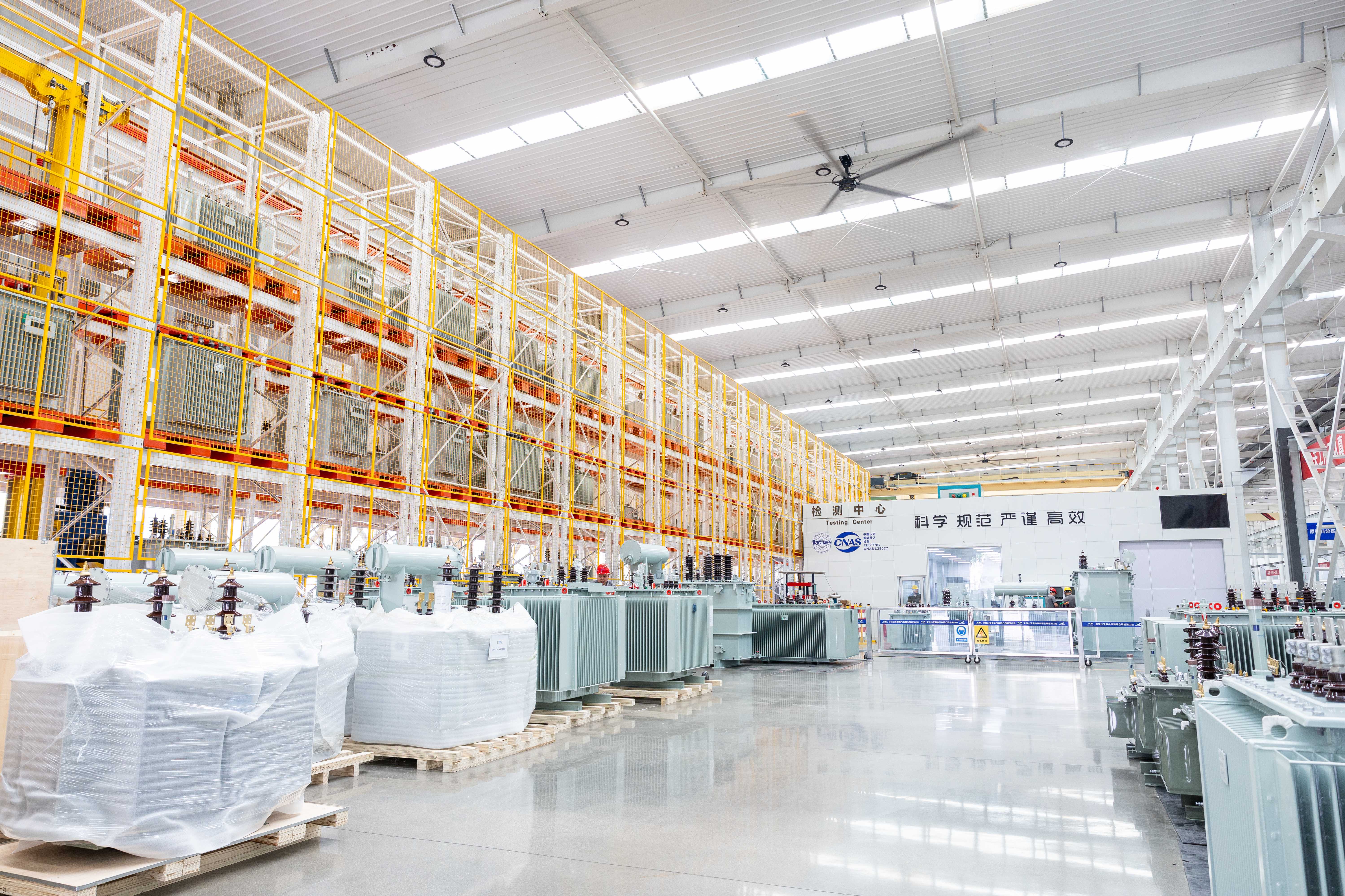
Each unit undergoes partial discharge measurement and induced voltage withstand tests tailored to 33/35kV class requirements, confirming insulation integrity under medium-high voltage stress beyond standard distribution-level checks.
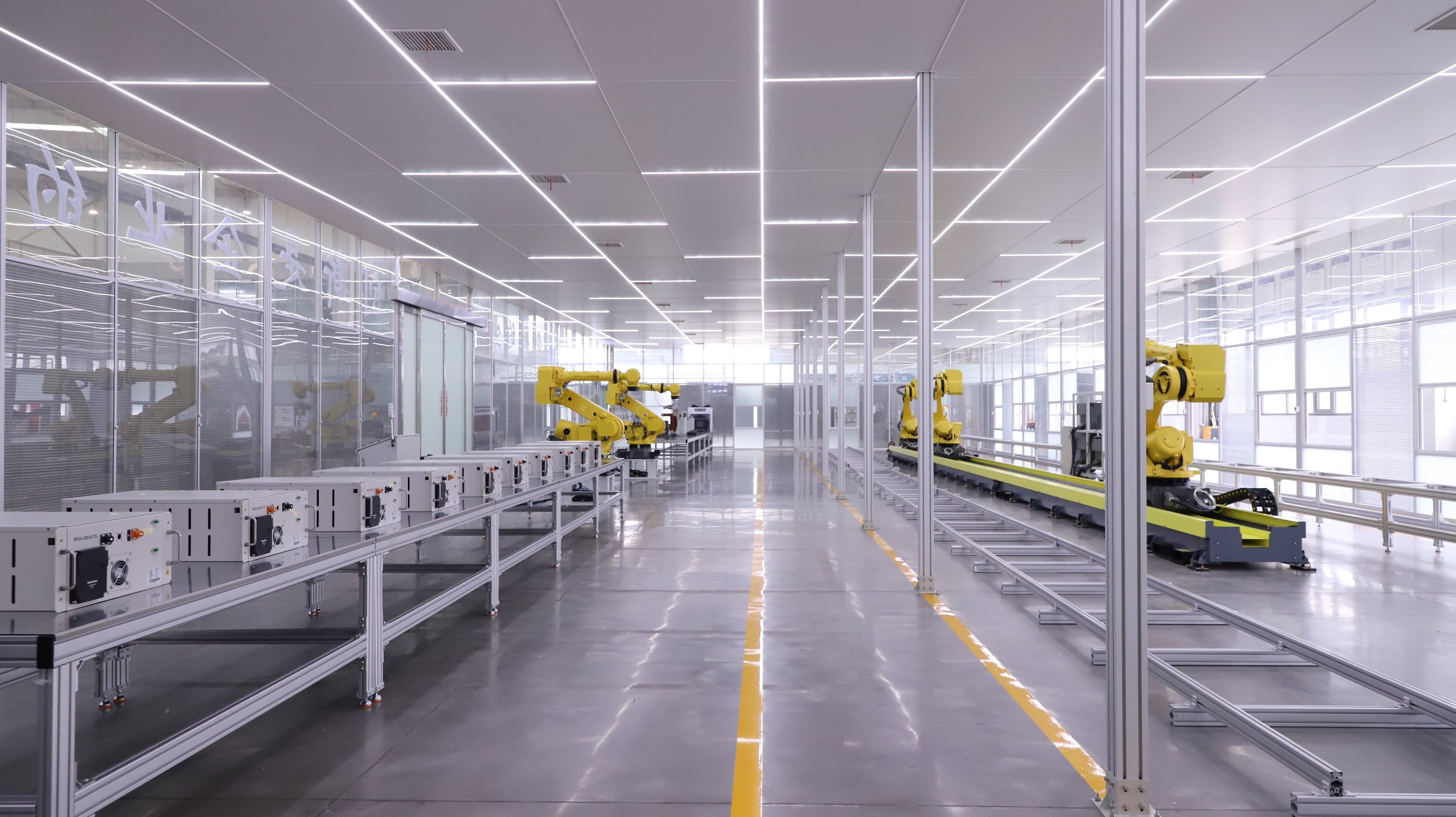
Units are tested against project-specific ambient temperature ranges, altitude corrections, and harmonic distortion profiles to guarantee rated performance under actual operating conditions, not just laboratory baselines.
|
Rated Capacity |
Voltage Combination |
Vector Group |
No-Load Loss(w) |
Load Loss |
No-Load Current (%) |
Short Circuit Impedance (%) |
||
|
High Voltage(kV) |
Tapping Range |
Low Voltage (kV) |
||||||
|
50 |
33 35
|
±5% ±2×2.5% |
0.4 |
Dyn 11 or Yyn0 |
170 |
1200 |
2.1 |
6.5 |
|
100 |
230 |
2010 |
2.0 |
|||||
|
125 |
270 |
2370 |
1.5 |
|||||
|
160 |
290 |
2820 |
1.4 |
|||||
|
200 |
340 |
3320 |
1.3 |
|||||
|
250 |
400 |
3950 |
1.2 |
|||||
|
315 |
480 |
4750 |
1.1 |
|||||
|
400 |
580 |
5740 |
1.0 |
|||||
|
500 |
680 |
6910 |
1.0 |
|||||
|
630 |
830 |
7860 |
0.9 |
|||||
|
800 |
980 |
9400 |
0.8 |
|||||
|
1000 |
1150 |
11500 |
0.7 |
|||||
|
1250 |
1400 |
13900 |
0.6 |
|||||
|
1600 |
1690 |
16600 |
0.6 |
|||||
|
2000 |
1990 |
19700 |
0.6 |
|||||
|
2500 |
2360 |
23200 |
0.6 |
|||||
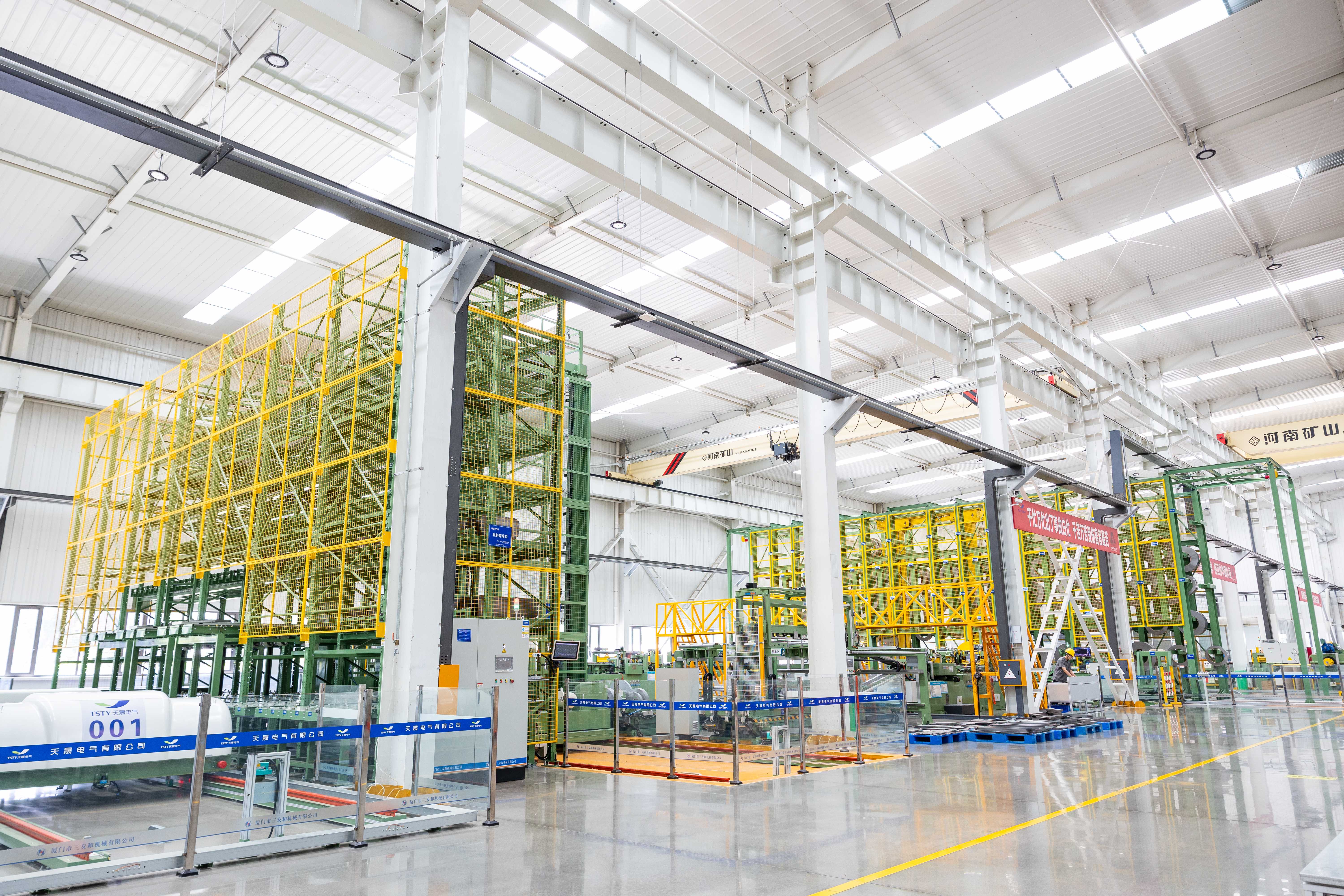
Choose between galvanized steel for standard outdoor durability or stainless steel for highly corrosive coastal/chemical plant environments; custom RAL color matching available for site aesthetics.
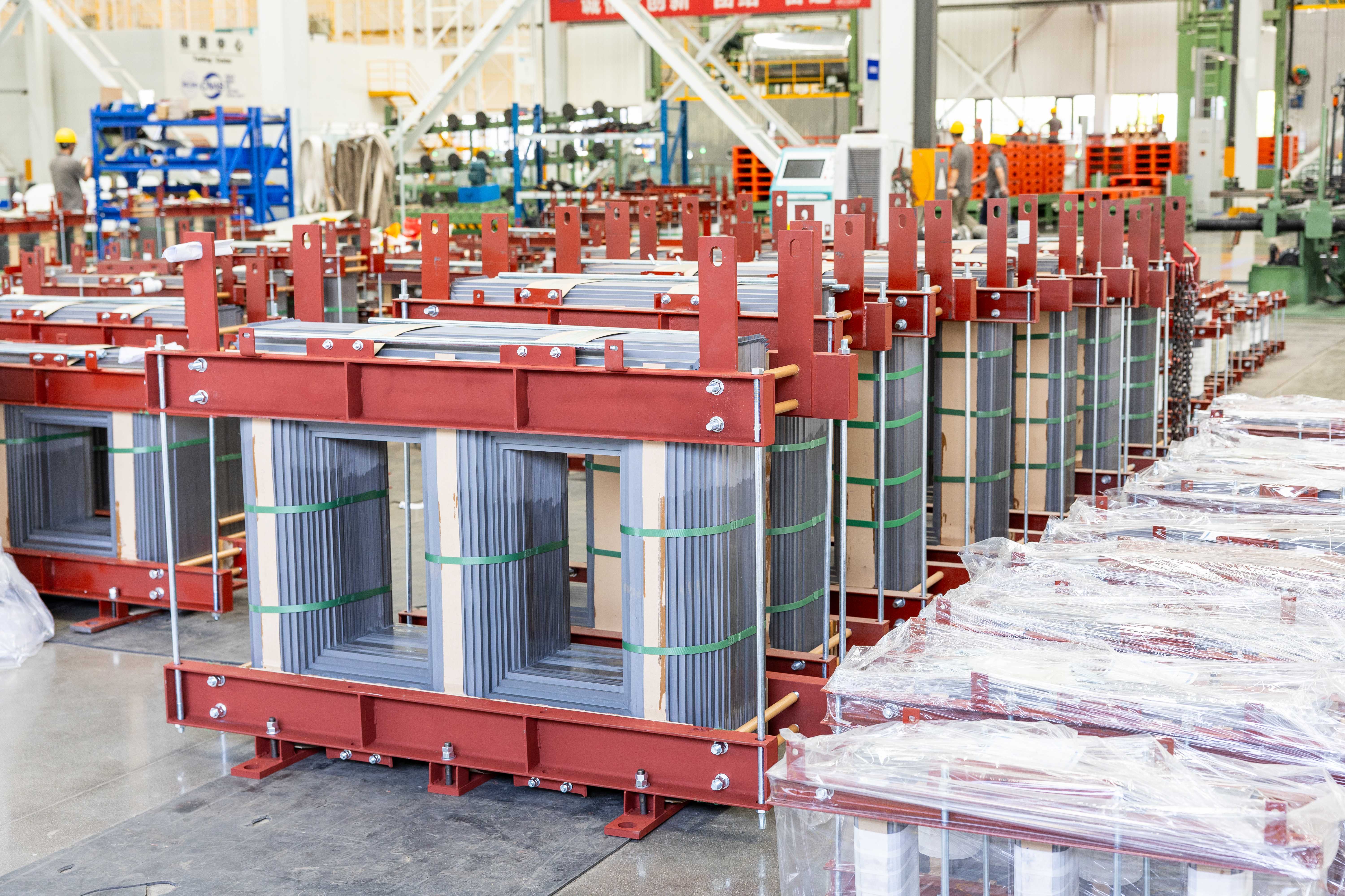
Select sealed-tank design for zero-maintenance operation in stable climates, or conservator with oil pillow for high-altitude or extreme-temperature sites requiring pressure equalization.
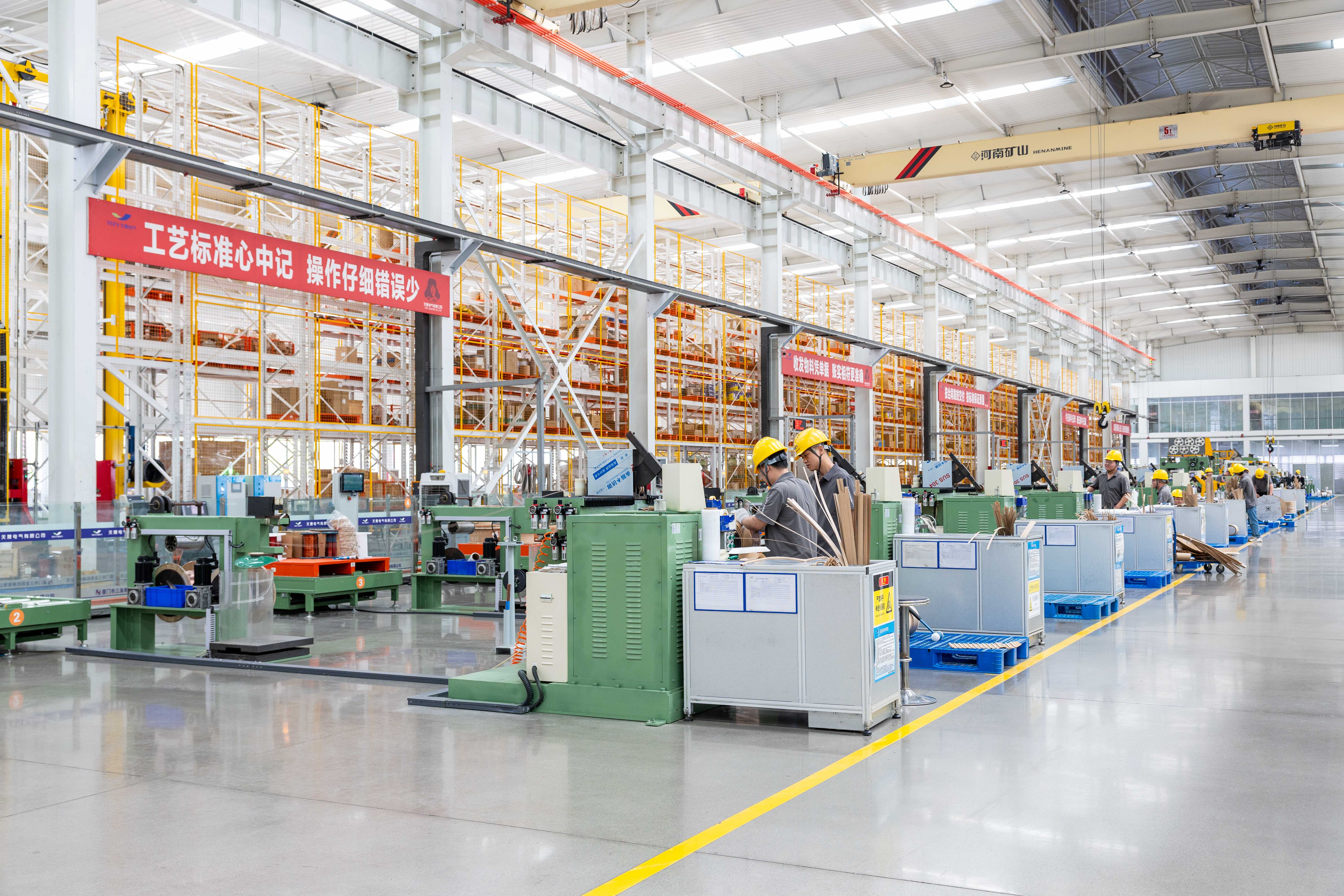
Specify off-circuit tap changer for fixed-ratio applications, or on-load tap changer (OLTC) with custom step voltages and position counts for dynamic grid support; tap ranges adjustable to match local utility tolerance bands.
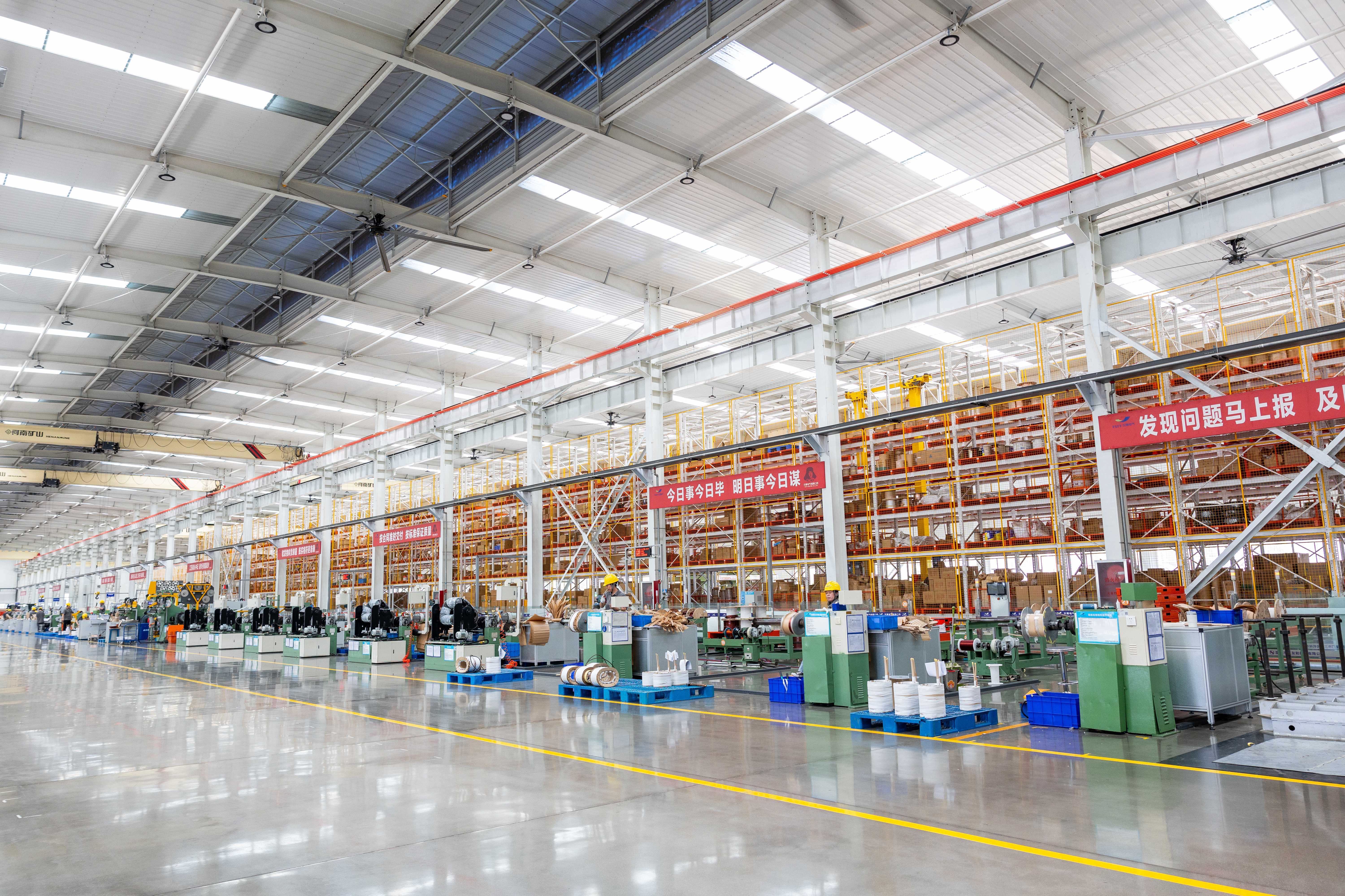
Opt for fully welded sealed enclosure to eliminate gasket maintenance, or add heavy-duty casters and jacking pads for indoor substation positioning where overhead cranes are unavailable.
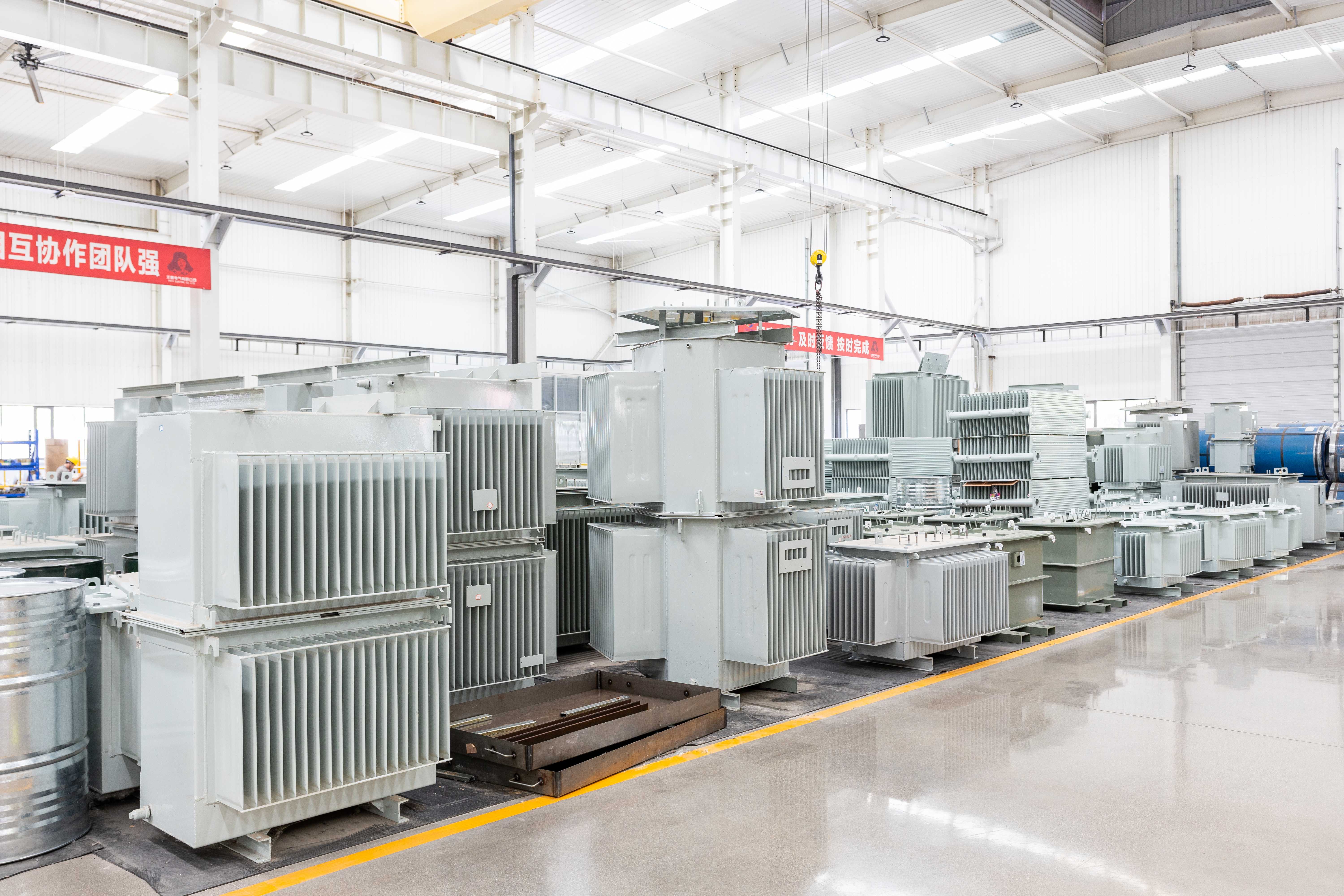
Add WTI/OTI sensors with analog/digital outputs and alarm/trip contacts for SCADA integration; optional gas-in-oil monitors available for early fault detection in critical assets.
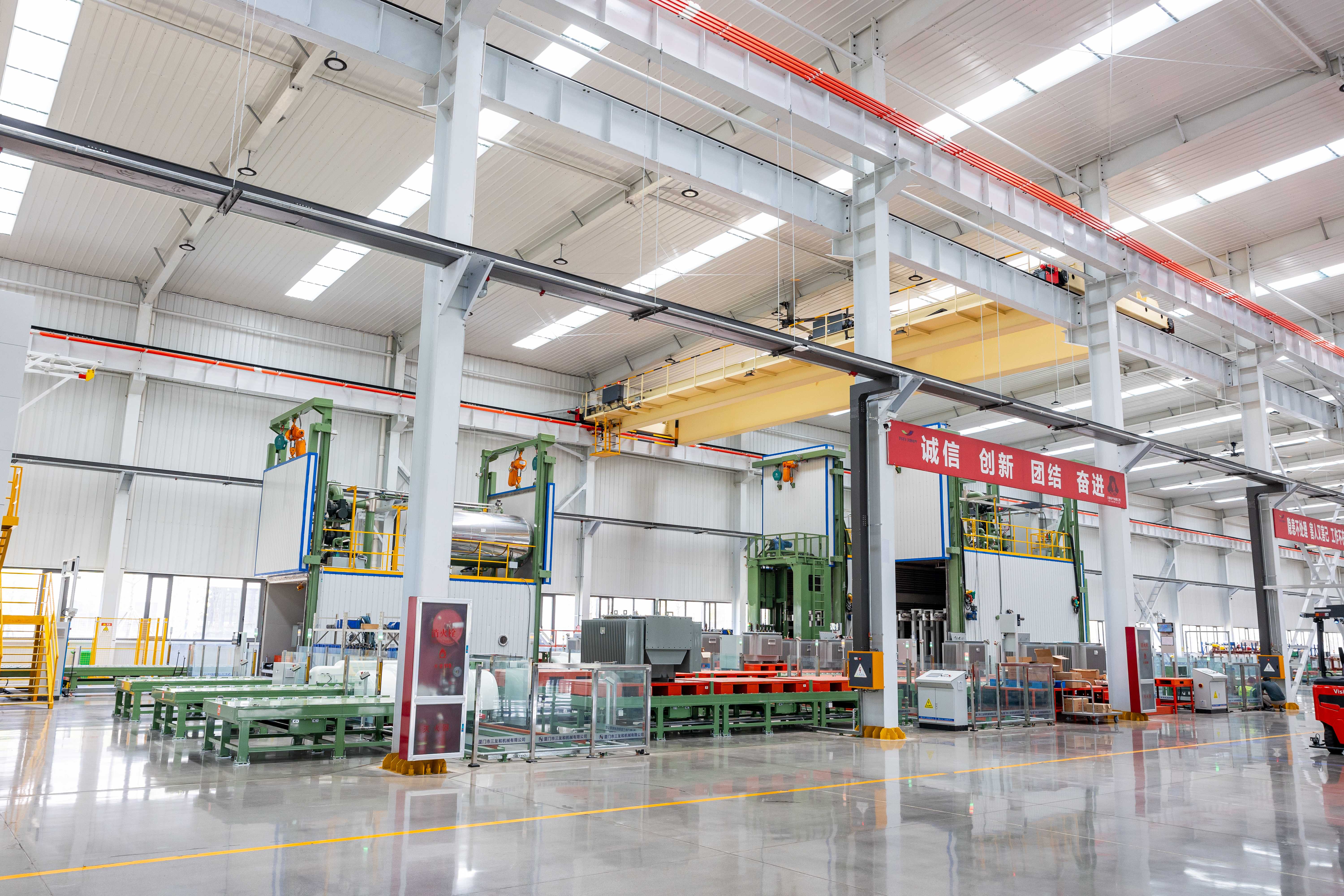
Customize no-load and load losses to meet project-specific lifecycle cost models or local regulatory tiers (e.g., S20/S22), rather than defaulting to generic efficiency classes.
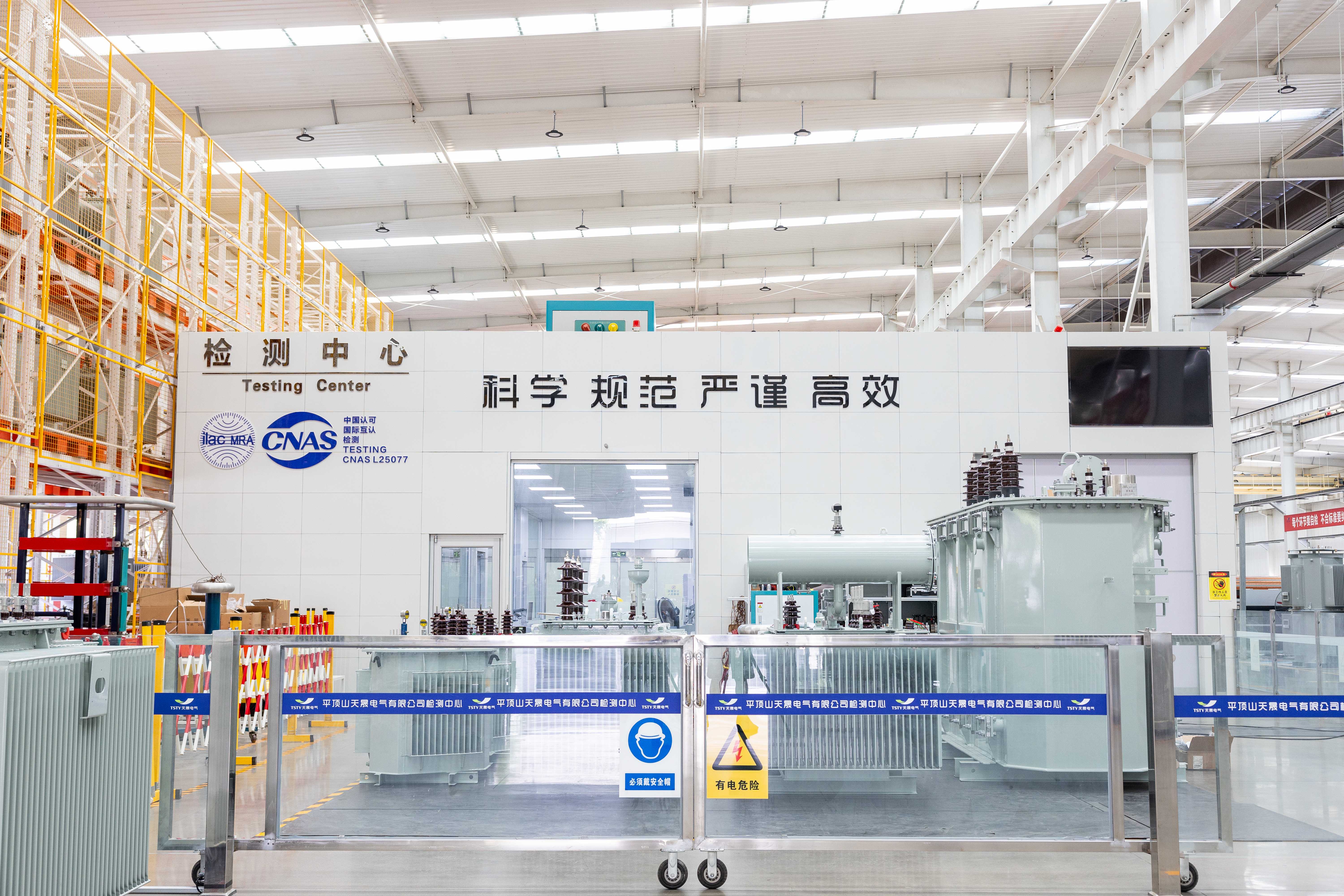
Adjust overall dimensions, bushing clearances, and mounting hole patterns to fit existing foundation footprints; nameplates available in bilingual formats or with QR codes linking to digital manuals.


Tell us your project requirements—voltage level, environment, grid code, or delivery timeline—and we’ll provide a compliant, optimized solution.





 EN