Grid Transformer Solutions for Utility Power Networks

Get a Free Quote

Our representative will contact you soon.
Select your project goal
Email
Name
Company Name
Phone
Project Details
0/1000
Grid Transformer Solutions for Power Transmission Networks

Grid Transformer Solutions for Power Transmission Networks

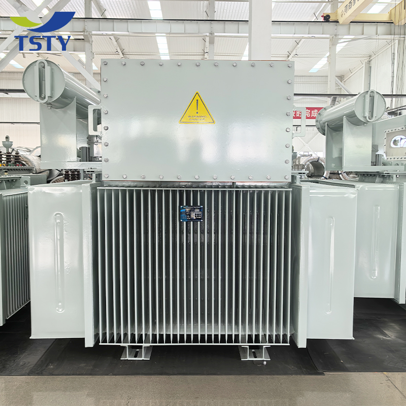
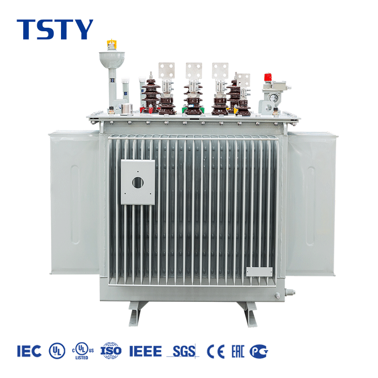
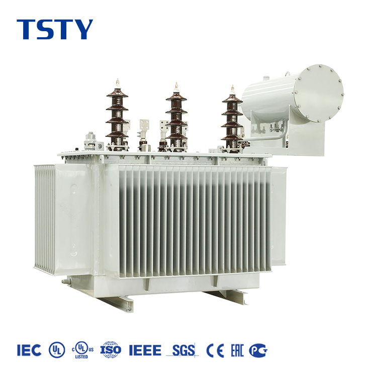
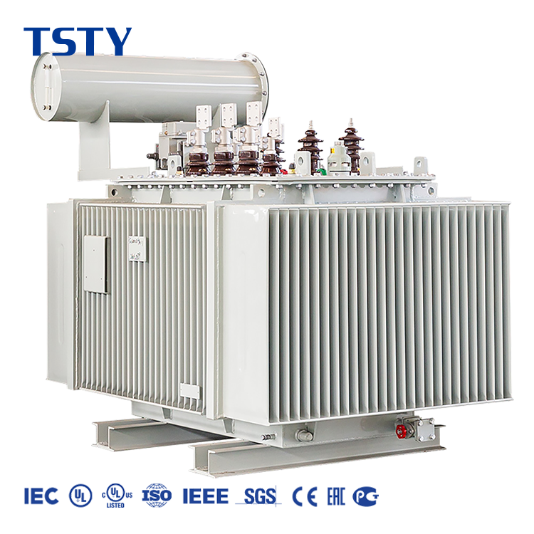
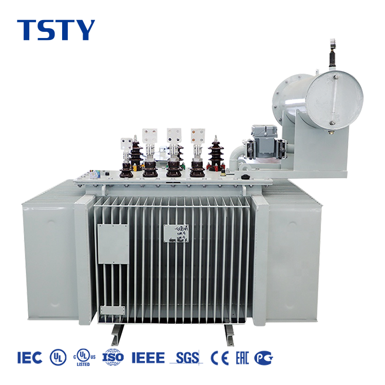
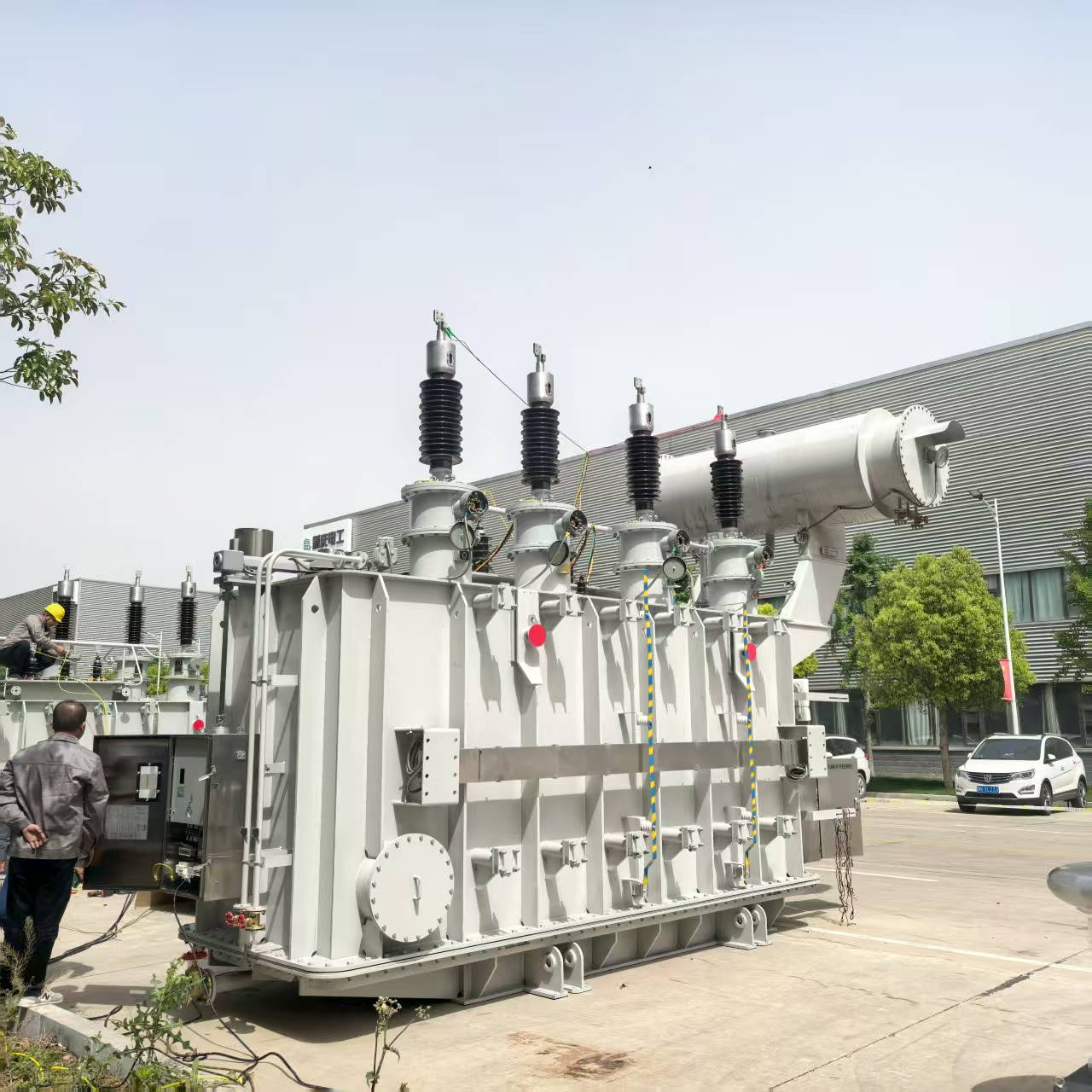
TSTY supplies grid transformer solutions for national transmission networks, regional utility substations, renewable energy integration systems, and large industrial power hubs. A grid transformer acts as a crucial link between different voltage levels, either stepping up voltage for long-distance transmission or stepping it down for local distribution. We provide oil-immersed power transformers, high voltage step-up transformers, and tie transformers designed according to specific utility codes. Our grid transformer configurations can be customized based on rated capacity, voltage ratio, frequency, vector group, short-circuit impedance, cooling method, and tap changer range. TSTY supports EPC contractors and utility operators with detailed technical drawings, routine factory testing, and systematic logistics planning to ensure reliable substation operation.
Get A Quote


Advantages of TSTY Grid Transformer Solutions

Reliable Voltage Conversion for Utility and Transmission Substation Projects

Grid-Compliant Voltage Ratios

Designed to match utility voltage requirements, ensuring the grid transformer seamlessly connects generation systems, transmission lines, and regional distribution networks.

Robust Short-Circuit Withstand

Each grid transformer is engineered to handle mechanical and thermal stresses during network fault conditions, maintaining structural and electrical system stability.

Flexible Cooling Arrangements

We offer ONAN, ONAF, and ODAF cooling methods based on transformer capacity and site environmental conditions to maintain safe operating temperatures.

Coordinated Protection Interfaces

The grid transformer can be equipped with gas relays, temperature indicators, and pressure relief devices for integration with substation SCADA and control systems.

Grid Transformer and Substation Power Equipment

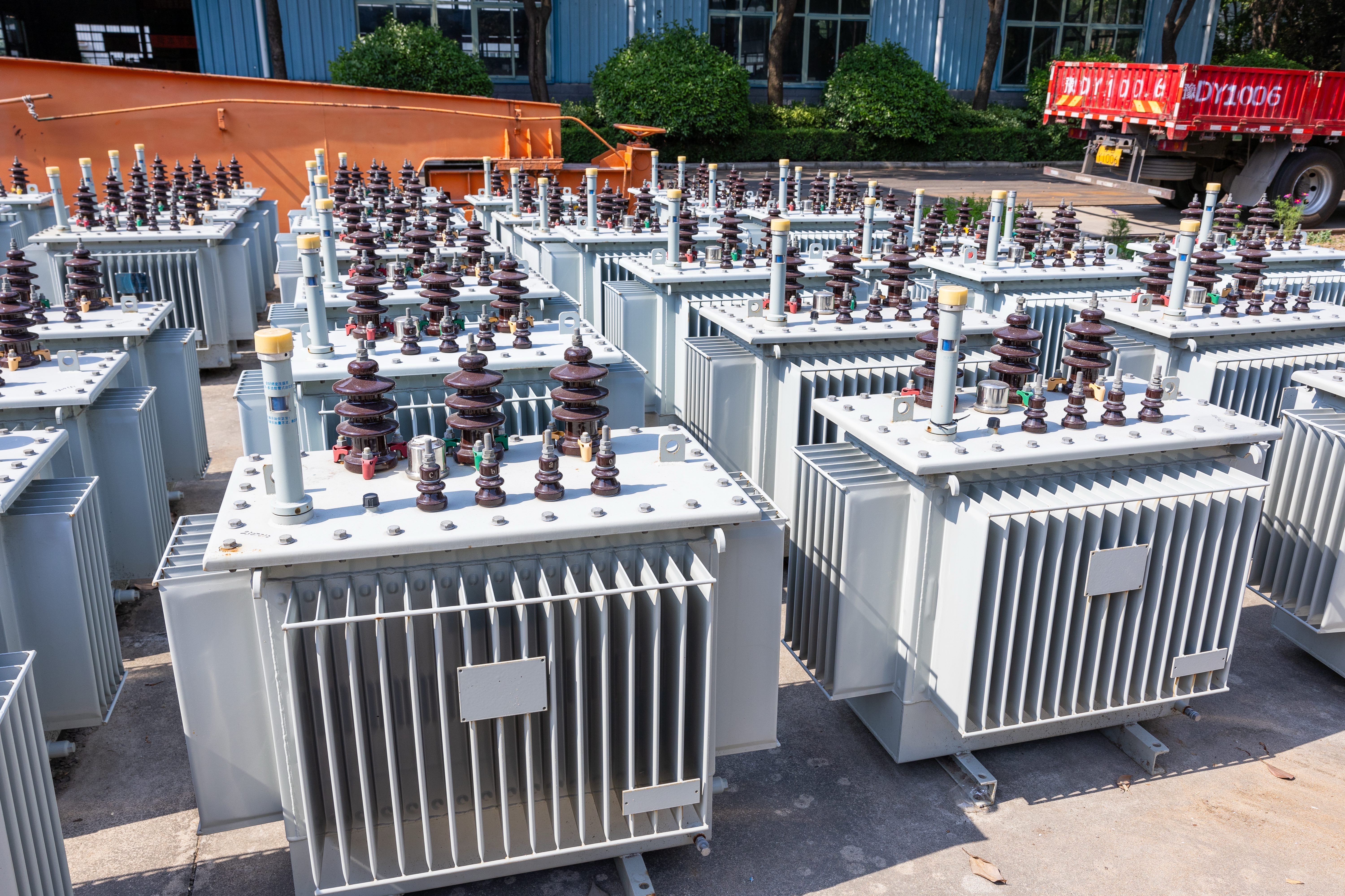
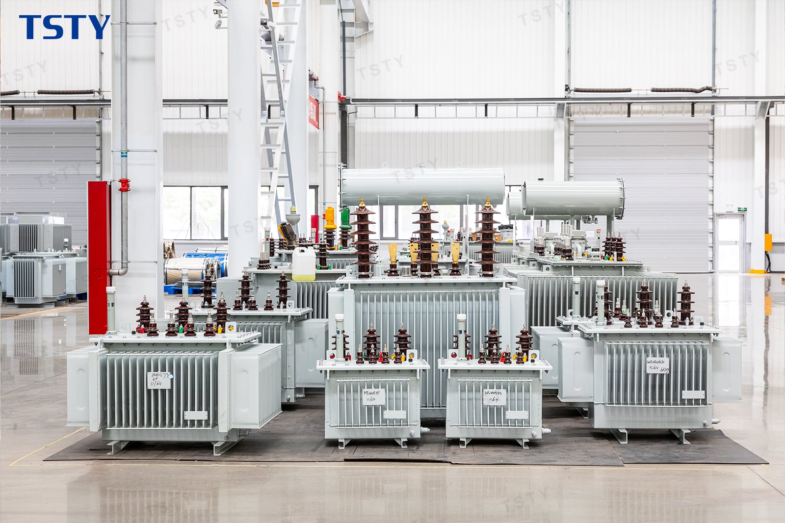
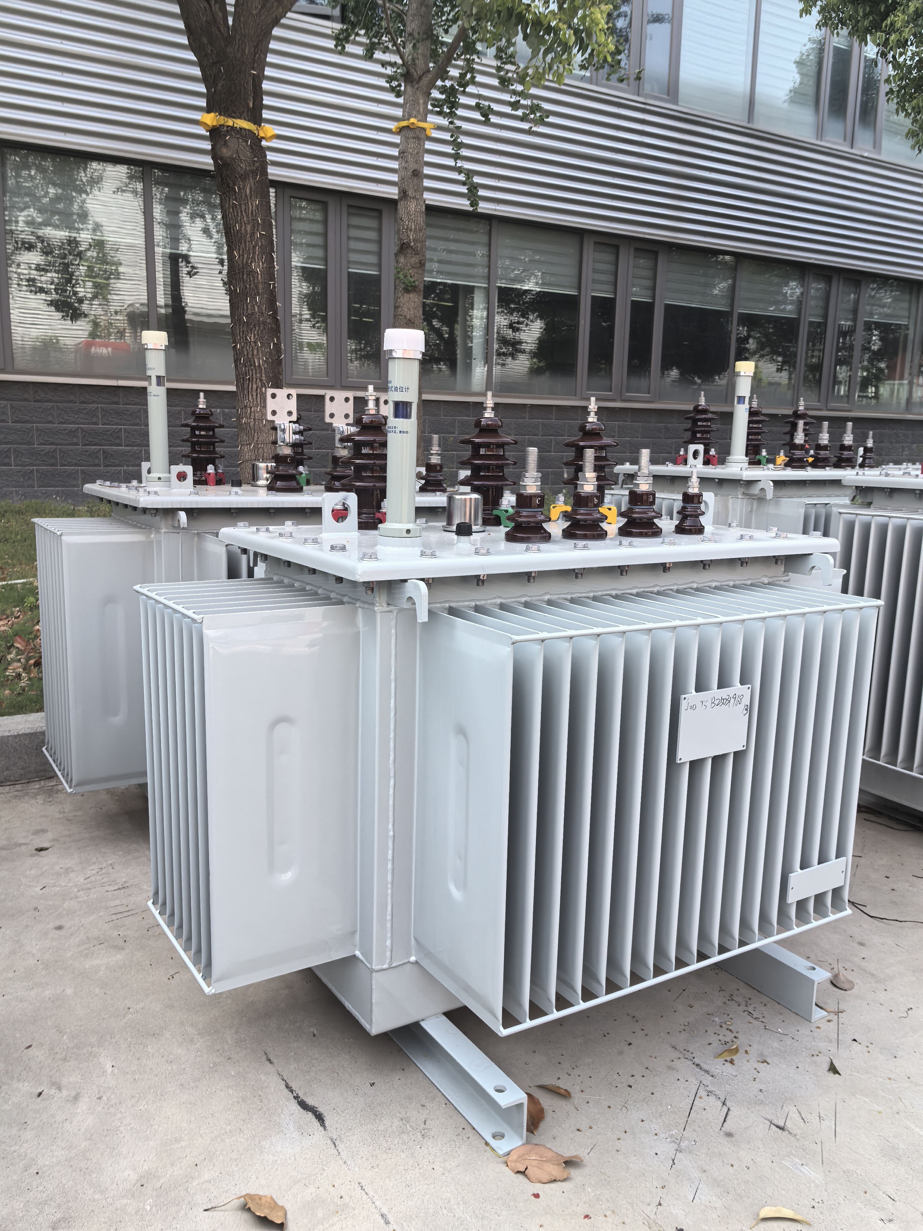
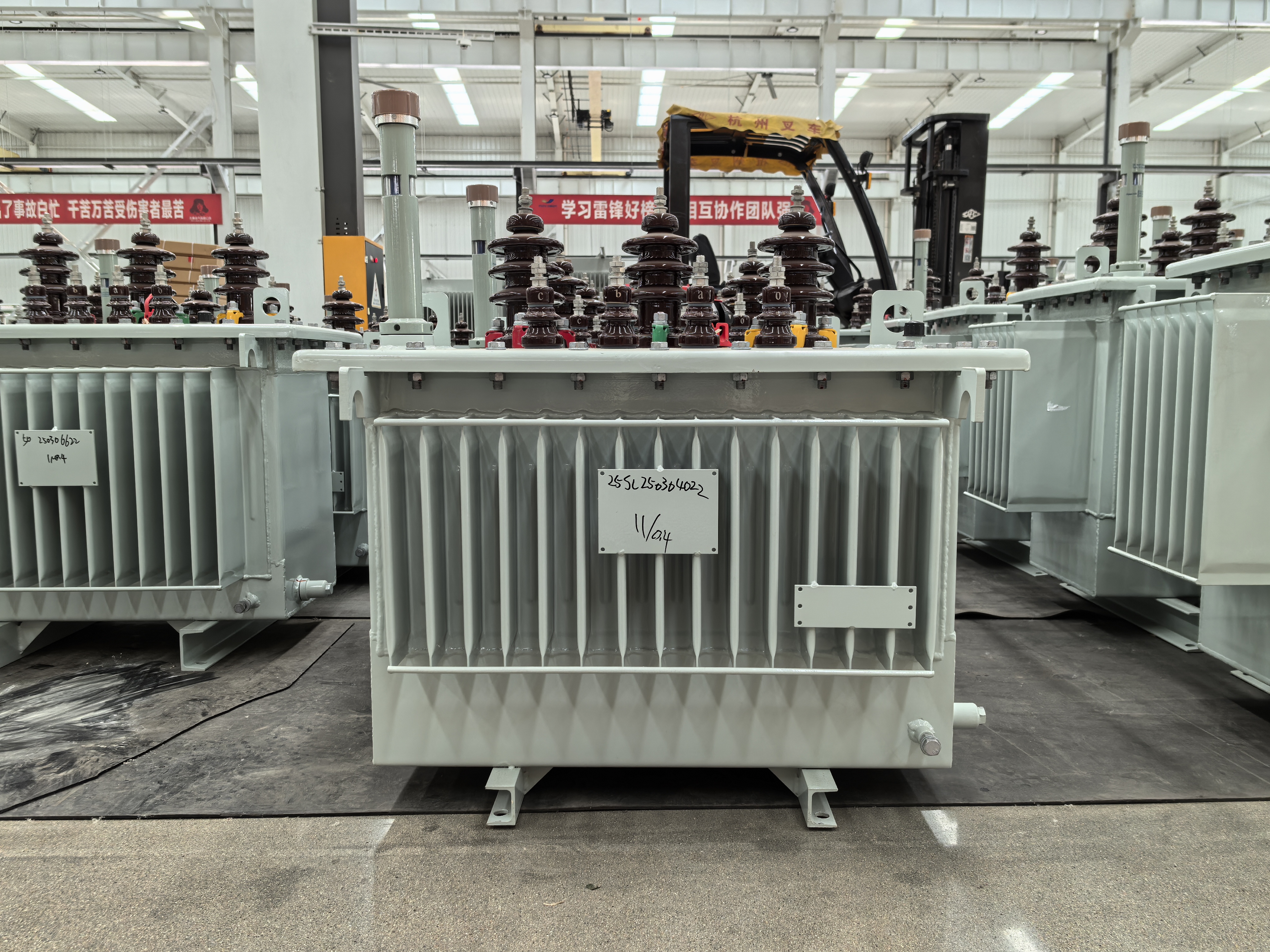
TSTY manufactures a comprehensive range of grid transformer products tailored for utility transmission and regional distribution networks. Our portfolio includes large oil-immersed power transformers, high voltage step-up transformers, step-down substation transformers, tie transformers, and renewable energy grid-connection transformers. A grid transformer can be specified with off-circuit or on-load tap changers (OLTC), standard or customized vector groups, and various bushing orientations. We also provide associated substation equipment, including high voltage switchgear, neutral grounding resistors, and control panels. Whether for a new utility switchyard or a substation upgrade project, our technical team coordinates the grid transformer specifications with the overall civil and electrical system design.

A grid transformer is a major electrical asset used within transmission and distribution networks to link circuits of different voltages. It allows power generated at lower voltages to be stepped up for efficient long-distance transmission, and then stepped down at receiving substations for industrial, commercial, or residential use.
The reliability of a grid transformer directly impacts the stability of the regional power supply. Therefore, utility companies and EPC contractors must strictly review technical parameters before manufacturing. Key specifications include rated power, primary and secondary voltages, number of phases, frequency, vector group, and impedance voltage. The tap changer—whether off-circuit (OCTC) or on-load (OLTC)—is also a critical component for regulating network voltage under varying load conditions without disrupting supply.

0392压缩.JPG
Because a grid transformer is typically installed in outdoor substations, environmental factors play a large role in its mechanical and insulation design. Buyers should specify site altitude, maximum and minimum ambient temperatures, humidity, and pollution levels. These details determine the required creepage distance for external bushings, anti-corrosion treatments for the tank, and the sizing of cooling radiators.
TSTY equips each grid transformer with necessary protection and monitoring accessories. Standard configurations often include a conservator tank with a silica gel breather, Buchholz relay for internal fault detection, oil and winding temperature indicators, pressure relief valves, and oil level gauges. These devices interface with the substation's control room to trigger alarms or trip breakers, preventing severe damage during abnormal conditions.
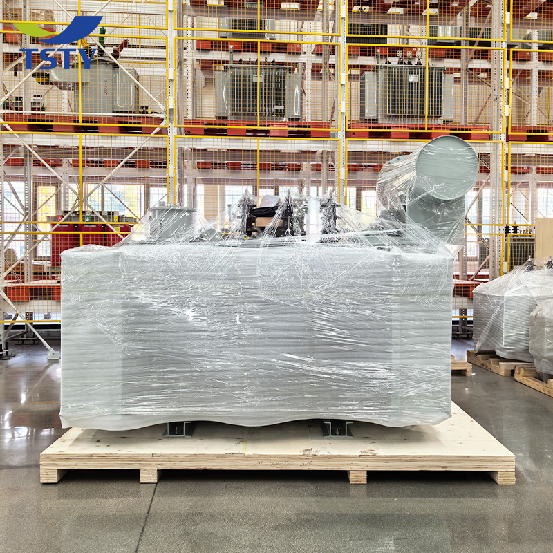
Transportation and site assembly present significant challenges for a large grid transformer. Due to weight and dimensional limits on highways, large capacity units are often shipped without oil, with the main tank filled with dry air or nitrogen. Radiators, bushings, and conservators are packed separately. TSTY provides detailed center of gravity diagrams, lifting instructions, and clear packing lists to support safe logistics, unloading, and site erection.
Before requesting a quotation, buyers should prepare a clear specification or single-line diagram. Important details include rated capacity, required voltage levels, cooling preference, tap range, installation environment, and any specific utility standards that must be met. Clear communication helps ensure the proposed equipment matches the power network's demands.

Frequently Asked Questions About Grid Transformer Selection

Common technical inquiries regarding parameters, installation, and utility project coordination.

What is the main function of a grid transformer?

A grid transformer connects different voltage levels within a power network, stepping voltage up for transmission or stepping it down for regional distribution substations.
An on-load tap changer (OLTC) adjusts the voltage ratio without disconnecting the transformer from the grid, while an off-circuit tap changer requires a power shutdown before manual adjustment.
Due to size and weight limits, it is usually shipped without oil and radiators. The main tank is filled with nitrogen or dry air, and accessories are assembled later on-site.
Buyers should provide installation altitude, ambient temperature range, wind speed, humidity, and site pollution levels to ensure proper insulation and cooling arrangements.
Yes, we provide protection accessories with electrical contacts (such as temperature indicators and gas relays) that connect directly to substation automation and control systems.
Standard tests include winding resistance, voltage ratio, vector group verification, impedance voltage, load and no-load losses, and dielectric withstand tests according to project standards.

Related Articles

Grid Transformer Solutions for Load Growth, Renewable Integration, and Network Reliability

28

Sep

Grid Transformer Solutions for Load Growth, Renewable Integration, and Network Reliability

Explore how a modern grid transformer handles load growth, renewable integration, and ensures network reliability for EPCs and utility substations.
View More
How to Match a 630 kVA Transformer with Real Load Demand and Future Expansion

09

Oct

How to Match a 630 kVA Transformer with Real Load Demand and Future Expansion

Learn how to match a transformer 630 kva with your facility's real load demand and future expansion. Expert sizing guide for B2B electrical procurement.
View More
1250 kVA Transformer for Heavy Commercial Loads and Industrial Power Distribution

09

Oct

1250 kVA Transformer for Heavy Commercial Loads and Industrial Power Distribution

Maximize ROI with a 1250 kVA transformer for industrial loads. Learn about harmonic mitigation, cooling, and TCO from a top B2B equipment manufacturer.
View More
How to Evaluate Power Transformer Manufacturers for Utility, Industrial, and EPC Projects

10

Oct

How to Evaluate Power Transformer Manufacturers for Utility, Industrial, and EPC Projects

Audit power transformer manufacturers for utility and EPC projects. Expert B2B guide on FAT protocols, core metallurgy, and assessing production capabilities.
View More

Client Feedback on Grid Transformer Projects

Practical experiences from utility engineers, EPC contractors, and project managers.
Julian Rossi
Substation Project Manager

“The grid transformer dimensions were provided early in the planning stage, allowing our civil team to finalize the concrete foundations and oil containment pit exactly on schedule.”

Sarah Jenkins
Utility Network Planner

“TSTY’s technical support helped us coordinate the on-load tap changer range with our regional voltage fluctuation requirements accurately, ensuring stable supply for the network.”

Khalid Al-Mansoori
EPC Lead Engineer

“Logistics for large substation equipment is always tough. The clear packing list and center of gravity details made lifting the grid transformer at the port much safer.”

Get a Free Quote

Our representative will contact you soon.
Select your project goal
Email
Name
Company Name
Phone
Project Details
0/1000
Voltage Regulation and Tap Changer Coordination

Voltage Regulation and Tap Changer Coordination

A grid transformer operates in dynamic networks where load demands and power generation levels change throughout the day. To maintain stable voltage at the receiving end, the tap changer mechanism is a highly critical component. Buyers must determine whether an off-circuit tap changer (OCTC) or an on-load tap changer (OLTC) is required based on grid operational rules. For a grid transformer equipped with an OLTC, the tapping range, number of steps, and control method must be carefully specified. TSTY assists project engineers in matching the tap changer characteristics with the anticipated voltage variations of the regional network. We also coordinate the control cabinet wiring with the substation automation system. By confirming these regulation parameters early, the utility can ensure continuous power quality without frequent manual interruptions, keeping the entire transmission system stable under varying conditions.
Managing Thermal Limits and Cooling Method Selection

Managing Thermal Limits and Cooling Method Selection

Operating continuously under heavy utility loads requires a grid transformer to have a highly effective cooling system. The selected cooling method directly impacts the transformer's physical footprint, load capacity, and maintenance routine. For standard applications, oil natural air natural (ONAN) cooling is utilized. As capacity increases, oil natural air forced (ONAF) or oil forced air forced (ODAF) methods may be implemented to dissipate heat more efficiently. When specifying a grid transformer, buyers need to provide clear data regarding maximum ambient temperature, installation altitude, and peak load cycles. TSTY reviews these environmental factors to optimize the radiator arrangement and fan sizing. A properly designed cooling system prevents insulation degradation caused by excessive temperature rise. This careful thermal management extends the operational lifespan of the equipment and minimizes the risk of unexpected outages in the power network.
Substation Layout Interface and Civil Integration

Substation Layout Interface and Civil Integration

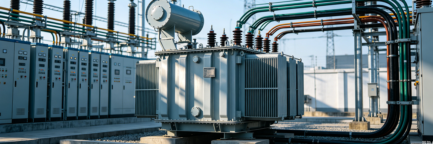
Integrating a grid transformer into a new or existing substation involves strict mechanical and civil coordination. Because these units are substantial in size and weight, physical interface details must be finalized before manufacturing begins. TSTY supplies comprehensive outline drawings indicating the precise locations of high and low voltage bushings, control boxes, oil drain valves, grounding pads, and jacking points. Project teams use this data to align the grid transformer with fire separation walls, oil containment basins, cable trenches, and overhead busbar structures. Furthermore, the positioning of cooling radiators and conservator tanks must allow adequate clearance for future maintenance access. Addressing these civil and mechanical interfaces during the initial design phase eliminates costly site modifications, streamlines the installation sequence, and ensures that the power facility meets all safety and environmental regulations.